External auditory canal cleaning tool

A cleaning tool and technology for the external auditory canal, applied in ear treatment, etc., can solve the problems of high energy consumption, skin damage, and high proportion of children, and achieve the effect of easy removal and reduced adhesion

Pending Publication Date: 2018-08-21
翟一舟
0 Cites 3 Cited by

AI-Extracted Technical Summary

Problems solved by technology

The existing ear pick structure includes a spoon handle and a spoon head, which is similar to a table spoon, but much smaller in size. When using it, hold the ear pick with one hand, and extend the spoon head into the external auditory canal to scrape off the cerumen And take it out, because it is impossible to directly observe the situation in the external auditory canal, so most of the time it is operated by feeling
This brings certain risks. For example, the spoon head can easily damage the skin of the external auditory canal, and even damage the tympanic membrane in severe cases.
Secondly, most of the existing ear picks are made of hard materials such as metal or plastic. Although the surface is polished, there is still a risk of damaging the skin for groups with delicate skin like young children, so many paren...

Method used

In other embodiments of the present invention, because the memory foam material is not suitable for cleaning, it needs to be replaced after a period of use, so the housing 5 can be evenly divided into two parts in the axial direction, and the two parts pass through the plug and the slot The detachable connection is realized, thereby facilitating the replacement of the second cork 17 and the second cork 21 .
The present invention adopts the mode of first softening and then clearing to remove cerumen, thereby cleaning the external auditory canal, the adhesion between the cerumen after softening and the skin of the external auditory canal is reduced, and ...

Abstract

The invention discloses an external auditory canal cleaning tool, comprising two cylindrical shells, wherein a linear output device is arranged in each shell, and comprises a driving plate rotationally arranged at a sealed end of the corresponding shell, each driving plate is exposed from an opening, and is coaxially and fixedly connected with a screw, a first movable seat sleeves each screw in amatched way, and is integrally connected with two sliders which are in one-to-one correspondence match with two chutes, each first movable seat is also fixedly connected with a second movable seat bya plurality of connecting rods, and the length of the connecting rods is greater than or equal to the length of the corresponding screw; the second movable seat of one linear output device is fixedlyconnected with a first soft plug, the second movable seat of the other linear output device is fixedly connected with a second soft plug, and both the diameter of the first soft plug and the diameterof the second soft plug are greater than the inner diameter of a reducing opening. According to the external auditory canal cleaning tool, a mode of softening firstly and clearing secondly is adopted,earwax in the external auditory canal can be thoroughly cleared away, and external auditory canal skin cannot be injured.

Application Domain

Ear treatment

Technology Topic

EngineeringExternal Auditory Canals +1

Image

  • External auditory canal cleaning tool
  • External auditory canal cleaning tool
  • External auditory canal cleaning tool

Examples

  • Experimental program(1)

Example Embodiment

[0025] The technical solutions in the embodiments of the present invention will be clearly and completely described below in conjunction with the accompanying drawings in the embodiments of the present invention. Obviously, the described embodiments are only a part of the embodiments of the present invention, rather than all the embodiments. Based on the embodiments of the present invention, all other embodiments obtained by those of ordinary skill in the art without creative work shall fall within the protection scope of the present invention.
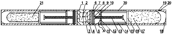
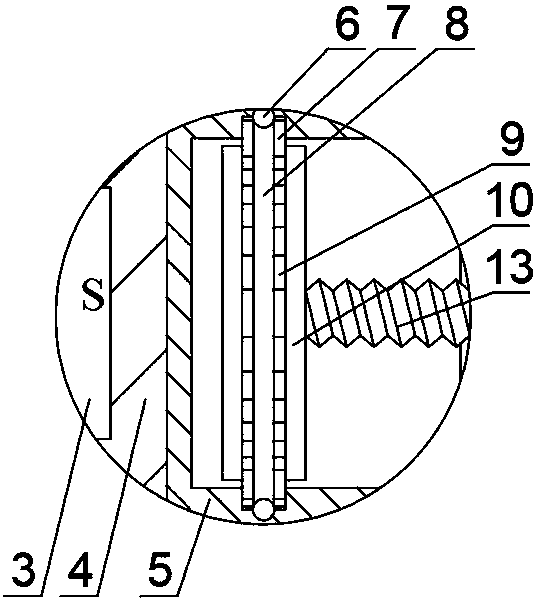
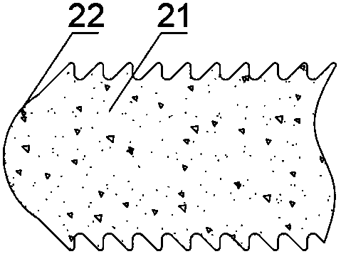
[0026] See Figure 1 to 5 , figure 1 Is a cross-sectional view of the overall structure of the present invention, figure 2 Yes figure 1 An enlarged view of part A in the middle, image 3 It is a schematic diagram of the second soft plug structure of the present invention, Figure 4 It is a schematic diagram of the connection between the housing and the dial of the present invention, Figure 5 It is a schematic diagram of the liquid addition bottle structure and the connection mode of the liquid addition bottle and the shell of the present invention.
[0027] An external auditory canal cleaning tool, comprising two cylindrical shells 5, one end of the shell 5 is closed, one of the closed ends of the shell 5 is fixedly connected with a first connecting seat 1, and the first connecting seat 1 is embedded with The closed end of the first permanent magnet 2 and the other housing 5 is fixedly connected to a second connecting seat 4, and a second permanent magnet 3 is embedded on the second connecting seat 4, and the first permanent magnet 2 and the second permanent magnet 3 pass The action of magnetic force realizes the detachable connection of the two shells 5. The other end of the housing 5 is provided with a reduced diameter opening 18, the inner wall of the housing 5 is provided with two sliding grooves 31 extending along the length direction, and a gap 24 is opened on the side wall of the housing 5 near the closed end.
[0028] Each of the two housings 5 ​​is provided with a linear output device. The linear output device includes a dial 7 that is rotatably arranged at the closed end of the housing 5. The dial 7 is exposed from the gap 24. The specific rotation setting is in the dial 7 An annular groove 8 is provided on the peripheral side wall of the, the dial 7 and the housing 5 are rotatably connected by a number of balls 6, a part of the balls 6 is embedded on the inner wall of the housing 5, and the other part of the balls 6 is set in the annular groove 8. In this way, a gap 23 is left between the dial 7 and the inner wall of the housing 5 while achieving the rotational connection. There are also two sets of friction blocks 9 fixedly arranged on the peripheral side wall of the dial 7, the friction blocks 9 are arranged in the gap 23, the two sets of friction blocks 9 are respectively located on both sides of the annular groove 8, and each group of friction blocks 9 is set to be several , A number of friction blocks 9 in each group are evenly distributed along the circumferential direction of the dial 7. A reinforcing block 10 is fixedly connected to both sides of the dial 7, and the reinforcing block 10 is in the shape of a disc. A reinforcing block 10 facing the reduced diameter opening 18 is coaxially fixed with a screw 13 and a matching sleeve on the screw 13 is provided with a second A movable seat 12, the first movable seat 12 is integrally connected with two sliders 11, the two sliders 11 are matched with the two sliding grooves 31 one by one, and the first movable seat 12 is also fixedly connected with a plurality of connecting rods 14 The length of the second movable seat 16 and the connecting rod 14 is greater than or equal to the length of the screw 13. The end of the screw 13 facing the reduced diameter opening 18 is also fixedly connected with a limit disk 15, and the diameter of the limit disk 15 is larger than the diameter of the screw 13.
[0029] The second movable seat 16 of one linear output device is fixedly connected with the first soft plug 17, and the second movable seat 16 of the other linear output device is fixedly connected with the second soft plug 21. The fixed connection between the second movable seat 16 and the first soft plug 17 or the second soft plug 21 may be to provide a clamping block on the second movable seat 16 and a block on the first soft plug 17 or the second soft plug 21 The card slot matched with the card block not only realizes a fixed connection, but also can replace the first soft plug 17 or the second soft plug 21. The first soft plug 17 has a cylindrical shape, and the end of the first soft plug 17 facing the reduced diameter opening 18 has a hemispherical shape. The second soft plug 21 is in the shape of a tower. The long side of the section of the second soft plug 21 forms a saw-tooth-like structure in the direction from the tip to the tail end. Each saw tooth is inclined to the tail end, and the bends are set in a circle. Angle, the tip of the tower shape is hemispherical to form a hemispherical head 22. The diameter of the first soft plug 17 and the diameter of the second soft plug 21 are both larger than the inner diameter of the reduced diameter opening 18. Both the first soft plug 17 and the second soft plug 21 are made of memory foam, preferably PU foam. The first soft plug 17 and its housing 5 and the corresponding linear output device together form a cerumen softening mechanism, and the second soft plug 21, its housing 5 and the corresponding linear output device together form a cerumen removal mechanism.
[0030] A part of the housing 5 near the reduced diameter opening 18 where the first soft plug 17 is located is also provided with a through hole 19, and a communicating head 20 is fixedly arranged in the through hole 19, and the communicating head 20 includes a fixed connection with the inner wall of the through hole 19 The duct base 30 and the duct 29 passing through the duct base 30.
[0031] It also includes a liquid addition bottle. The liquid addition bottle includes a screw-connected bottle bottom 25 and a bottle body 26. The bottle body 26 is also integrally connected with a conical bottle mouth 27. The inside of the bottle mouth 27 is fixed with a one-way valve 28, and The conduction direction of the valve 28 is from the bottle mouth 27 to the bottle bottom 25.
[0032] The method of use of the present invention is as follows.
[0033] Step 1: Use the cerumen softening mechanism to soften the cerumen in the external auditory canal, thereby facilitating the removal of the cerumen.
[0034] First, add a solution for softening the cerumen into the liquid addition bottle, which can be physiological saline. The specific method is to separate the bottom 25 and the body 26 by rotating the bottom 25, then add the solution to the bottom 25, and then re The bottle bottom 25 and the bottle body 26 are installed. Because the bottle mouth 27 is provided with a one-way valve 28, the solution will not flow out of the liquid adding bottle. Secondly, the catheter 29 is inserted into the bottle mouth 27, and the catheter 29 conducts the one-way valve 28 so that the solution can flow along the catheter 29 into the housing 5 where the first soft plug 17 is located. After that, the dial 7 of the linear output device connected to the first soft plug 17 is moved to drive the screw 13 to rotate. Through the cooperation of the screw 13 and the first movable seat 12, the first movable seat 12 is driven to the reduced diameter opening 18. The first movable seat 12 drives the second movable seat 16 and the first soft plug 17 to move in the direction of the diameter-reducing opening 18 through the connecting rod 14. The first soft plug 17 drips through the conduit 29 during the movement. On the first soft stopper 17, the first soft stopper 17 is infiltrated, but because only one side of the first soft stopper 17 is infiltrated, the solution is not evenly distributed in the first soft stopper 17. As the soft plug 17 continues to move, the first soft plug 17 starts to protrude from the reduced diameter opening 18. Because the diameter of the reduced diameter opening 18 is smaller than the diameter of the first soft plug 17, the first soft plug 17 will be compressed. The gas in the first soft plug 17 is squeezed out, and the solution with less content can be retained and evenly distributed in the first soft plug 17. Because it is made of memory foam, the first soft plug 17 is removed from the shell After the body 5 is extended, it continues to maintain the compressed state. At this time, the first soft plug 17 is extended into the external auditory canal. As air continues to enter, the first soft plug 17 gradually expands and returns to its original size, and fits with the external auditory canal. The solution in the first soft plug 17 will infiltrate the cerumen, thereby realizing the softening of the cerumen.
[0035] Step two, use the cerumen removal structure to remove the cerumen from the external auditory meatus.
[0036] Similar to step 1, the second soft plug 21 is driven to protrude from the housing 1 by rotating the dial 7 of the linear output device connected to the second soft plug 21. When the second soft plug 21 passes through the reducing buckle 18 After being compressed, the protruding part of the second soft plug 21 is inserted into the external auditory canal, and then the second soft plug 21 inhales air to expand and restore. The expanded second soft plug 21 fits on the external auditory canal, and then pulls the first soft plug outward. Two soft plugs 21, the tower-shaped outer wall of the second soft plug 21 can continuously peel the softened cerumen from the external auditory canal, and the cerumen is temporarily stored in the recessed part of the outer wall, as the second soft plug 21 is pulled , Can completely remove the cerumen in the external auditory canal and take it out of the external auditory canal.
[0037] The invention adopts the method of first softening and then clearing to remove the cerumen, so as to clean the external ear canal. The adhesive force between the softened cerumen and the skin of the external ear canal is reduced, and it is easier to remove, and the removal process will not cause damage to the external ear canal. . At the same time, the present invention uses the first soft plug 17 and the second soft plug 21 made of memory foam as tools for softening and taking out the cerumen, which will not cause damage to the skin of the external auditory canal when directly contacting the skin of the external auditory canal, and the first soft plug 17 and the second soft plug 21 can fully fit with the external auditory canal during the expansion process, so as to ensure that the softening of the cerumen and the removal of the cerumen can be very thorough, and there will be no residue.
[0038] In summary, the present invention can completely remove the cerumen of the external auditory canal without causing damage to the skin of the external auditory canal, and is particularly suitable for infants with delicate skin.
[0039] In other embodiments of the present invention, because the memory foam material is not suitable for cleaning, it needs to be replaced after a period of use. Therefore, the housing 5 can be divided into two parts evenly along the axial direction, and the two parts are detachable by inserting blocks and slots. Connection, thereby facilitating the replacement of the second soft plug 17 and the second soft plug 21.
[0040] It should also be noted that in this article, relational terms such as first and second are only used to distinguish one entity or operation from another entity or operation, and do not necessarily require or imply these entities or operations. There is any such actual relationship or order between. Moreover, the terms "include", "include" or any other variants thereof are intended to cover non-exclusive inclusion, so that a process, method, article or device including a series of elements not only includes those elements, but also includes those that are not explicitly listed Other elements of, or also include elements inherent to this process, method, article or equipment. If there are no more restrictions, the element defined by the sentence "including a..." does not exclude the existence of other same elements in the process, method, article, or equipment including the element.
[0041] The foregoing description of the disclosed embodiments enables those skilled in the art to implement or use the present invention. Various modifications to these embodiments will be obvious to those skilled in the art, and the general principles defined in this document can be implemented in other embodiments without departing from the spirit or scope of the present invention. Therefore, the present invention will not be limited to the embodiments shown in this document, but should conform to the widest scope consistent with the principles and novel features disclosed in this document.

PUM

no PUM

Description & Claims & Application Information

We can also present the details of the Description, Claims and Application information to help users get a comprehensive understanding of the technical details of the patent, such as background art, summary of invention, brief description of drawings, description of embodiments, and other original content. On the other hand, users can also determine the specific scope of protection of the technology through the list of claims; as well as understand the changes in the life cycle of the technology with the presentation of the patent timeline. Login to view more.

Similar technology patents

Device and method of melting polysilicon powder by electron beam

InactiveCN104402000Aeasy to removeShorten smelting time
Owner:DALIAN UNIV OF TECH

Fixed-point cleaning machine for fabric

Owner:上海仕操洗涤有限公司

Classification and recommendation of technical efficacy words

  • Easy to remove

Ocean fishing vessel propeller

ActiveCN104828229AIncrease cutting powereasy to remove
Owner:ZHOUSHAN WONDERFUL MARINE DESIGN CO LTD
Why Eureka
Try Eureka