Flexible reuse type optical storage charging intelligent charging station based on high-voltage direct-current microgrid

A high-voltage DC, charging station technology, applied in charging stations, AC network circuits, photovoltaic power generation and other directions, can solve problems such as short-term load impact of the power grid, and achieve the effect of maintaining stable operation, realizing flexible charging, and improving system operation efficiency.

Pending Publication Date: 2021-04-13
STATE GRID HUBEI ELECTRIC POWER RES INST +1
View PDF2 Cites 1 Cited by
  • Summary
  • Abstract
  • Description
  • Claims
  • Application Information

AI Technical Summary

Problems solved by technology

[0004] The purpose of the present invention is to provide a flexible and reusable optical-storage-charge smart charging station based on high-voltage DC micro-grid, which solves the problem of short-term load impact on the power grid during peak load periods in the prior art

Method used


Image

  • Flexible reuse type optical storage charging intelligent charging station based on high-voltage direct-current microgrid
  • Flexible reuse type optical storage charging intelligent charging station based on high-voltage direct-current microgrid
  • Flexible reuse type optical storage charging intelligent charging station based on high-voltage direct-current microgrid

Examples


Embodiment Construction

[0021] In order to make the purpose, technical solutions and advantages of the embodiments of the present invention clearer, the technical solutions in the embodiments of the present invention will be clearly and completely described below in conjunction with the drawings in the embodiments of the present invention. Obviously, the described embodiments It is a part of embodiments of the present invention, but not all embodiments. Based on the embodiments of the present invention, all other embodiments obtained by persons of ordinary skill in the art without making creative efforts belong to the protection scope of the present invention.

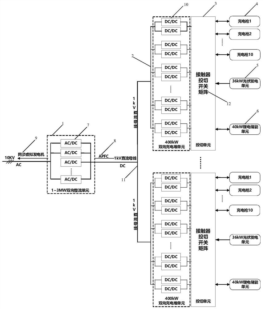
[0022] see figure 1 , one of the embodiments of the present invention based on the high-voltage direct current micro-grid flexible multiplexing optical storage charging smart charging station, including a bidirectional rectification unit 1 (1-3MW), a bidirectional charging stack unit 2 (400kW), a switching unit 3, a charging Gun 4, photovolt...


PUM


Abstract

The invention provides a flexible reuse type optical storage charging intelligent charging station based on a high-voltage direct-current microgrid. The system comprises a bidirectional rectification unit, a bidirectional charging pile unit, a switching unit, a charging gun, a photovoltaic power generation unit and an energy storage unit. The bidirectional rectification unit is connected with a 10kV AC power distribution network upwards, and converges with the bidirectional charging pile unit downwards at a 1kV DC bus. The switching unit is connected with the indoor machine room bidirectional charging pile unit, the energy storage unit, the outdoor charging guns and the photovoltaic power generation unit at the same time. Different direct-current charging and discharging channels are established by using a contactor fling-cut switch matrix, and different control strategies are adopted according to the charging power of the electric vehicle, so that the flexible charging of the electric vehicle can be realized; the power utilization of the fast charging station in the daytime load peak period is supported, and a photovoltaic power generation system is added for supplementation, so that the load peak-valley difference of the fast charging station can be effectively balanced, the peak clipping and valley filling effects are achieved, the stable operation of the power grid operation state is maintained, and the system operation efficiency is improved.

Description

technical field [0001] The invention relates to the technical field of new energy photovoltaic energy storage charging stations, in particular to a flexible and reusable optical storage charging smart charging station and a control method based on a high-voltage DC microgrid. Background technique [0002] At present, the electric vehicle charging station has a single power supply, mainly in the form of power supply through the distribution network. There are usually multiple DC chargers in the station. Due to the high power of a single DC charger, the single charging time is short. During the peak load period of the power grid, if a large number of electric vehicles need fast charging at the same time, the high-power charging demand will bring a short-term load impact on the power grid. With the large-scale construction of charging stations, this problem will inevitably affect the stable operation of the power grid, and may even threaten the security of the power system. ...

Claims


Application Information

Patent Timeline
IPC IPC(8): H02J3/32H02J3/38H02M3/335H02M7/219B60L53/51B60L53/63B60L53/67B60L55/00
CPCH02J3/322H02J3/381H02M3/33584H02M3/33523H02M7/219B60L53/51B60L53/63B60L53/67B60L55/00H02J2300/24H02J2310/48Y02T10/70Y02T10/72Y02T10/7072Y02T90/12Y02E10/56Y02E70/30
Inventor 向慕超凌在汛崔一铂金晨康逸群陈文游力熊昊哲丁永明万冲
Owner STATE GRID HUBEI ELECTRIC POWER RES INST
Why Eureka
Try Eureka