Dust-dirt separation device and dust collector

A technology for separating devices and dust. It is applied in the installation of vacuum cleaners, suction filters, and electrical equipment. It can solve the problems of easy damage and other problems, and achieve the effects of reducing occupied space, improving user experience, and low power consumption.

Pending Publication Date: 2021-04-16
GREE ELECTRIC APPLIANCES INC
View PDF0 Cites 1 Cited by
  • Summary
  • Abstract
  • Description
  • Claims
  • Application Information

AI Technical Summary

Problems solved by technology

[0007] Therefore, the technical problem to be solved by the present invention is to overcome the defect that the dirt separator in the prior art is prone to damage after being impacted by the air flow carrying large mass particles

Method used


Image

  • Dust-dirt separation device and dust collector
  • Dust-dirt separation device and dust collector
  • Dust-dirt separation device and dust collector

Examples


Embodiment 1

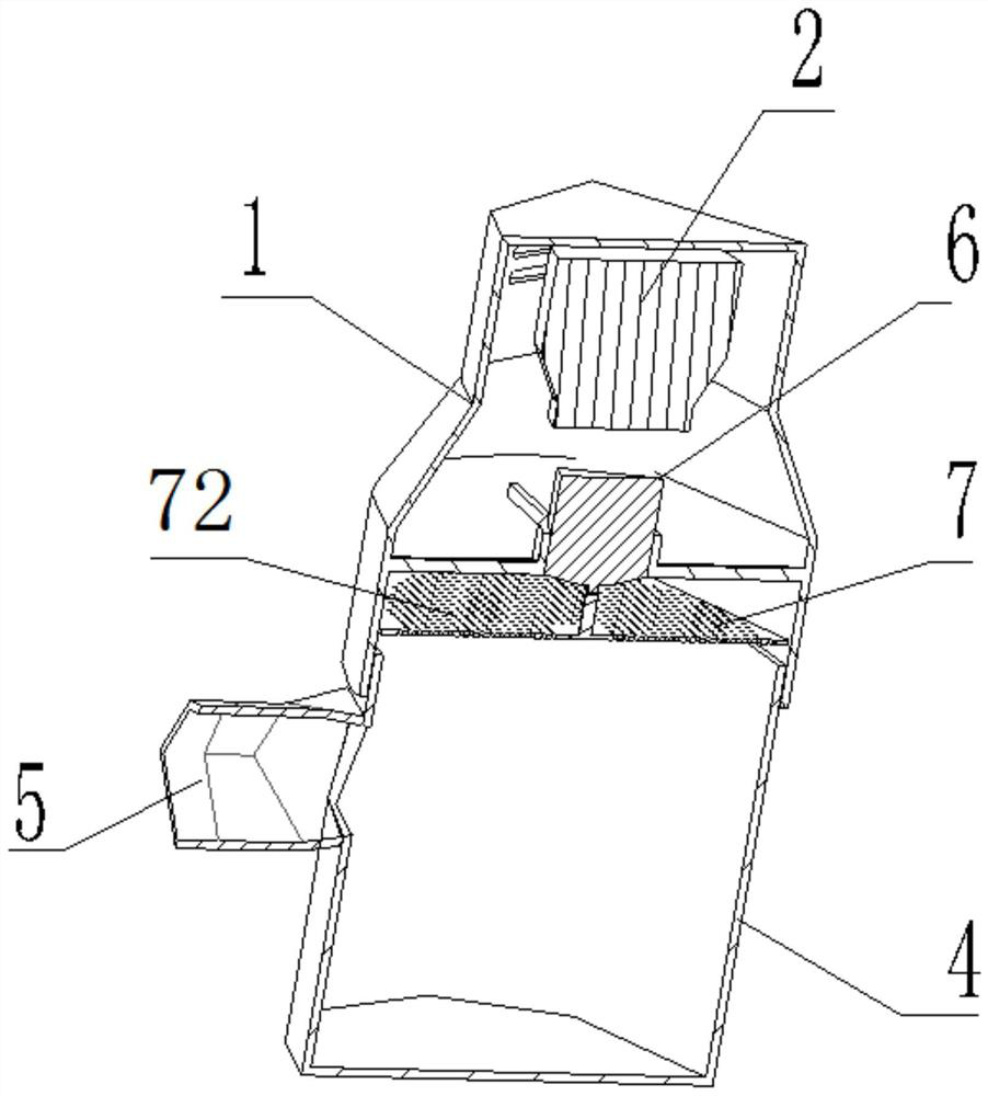
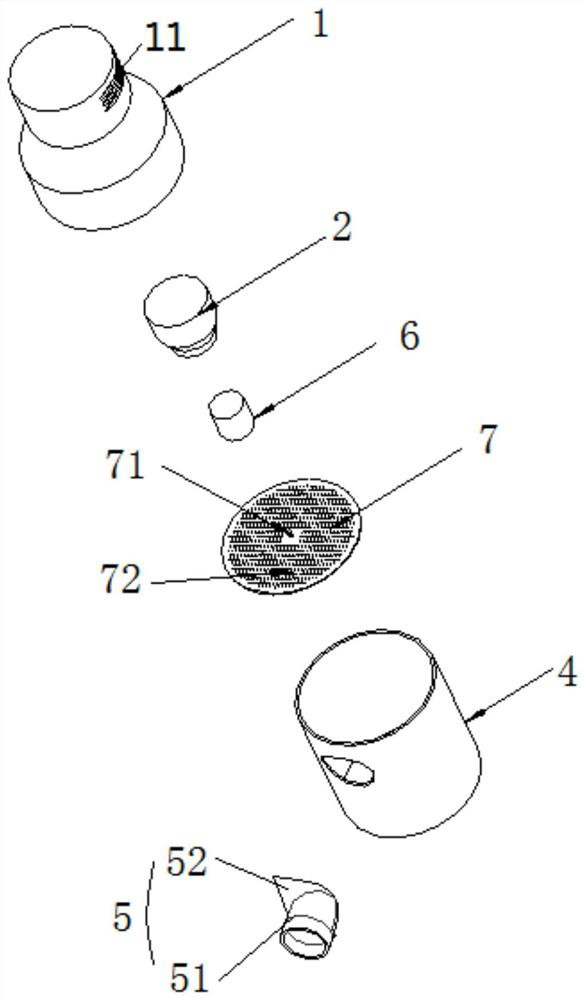
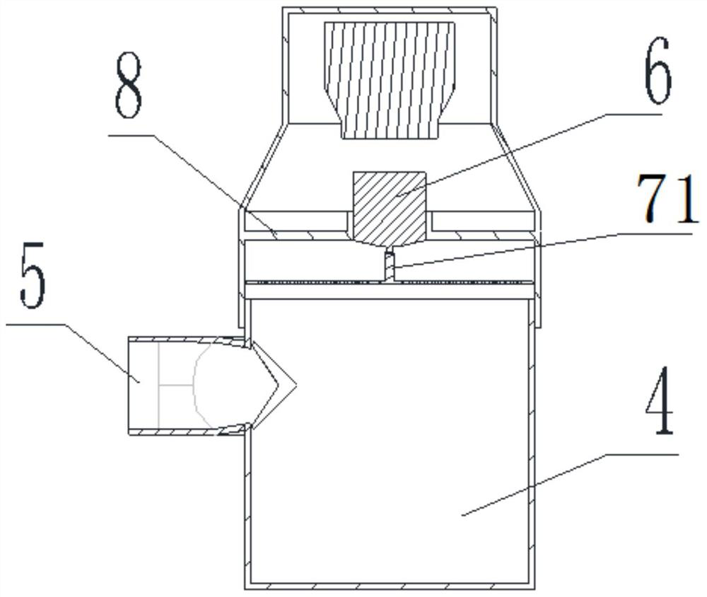
[0043] This embodiment provides a dust and dirt separation device, such as Figure 1-Figure 3 shown, including:

[0044] The main body 1 is provided with a vacuum motor 2 inside;

[0045] The wind wheel is detachably arranged on the vacuum motor 2; in this embodiment, the wind wheel is integrated inside the vacuum motor, and a through hole is provided on the housing of the vacuum motor 2, so as to realize the suction operation;

[0046] Specifically, the main body 1 itself adopts a cylindrical arrangement, the vacuum motor 2 itself is connected to an external power source, the center of the wind wheel is connected to the output shaft of the vacuum motor 2, and the output shaft is detachably connected to the center of the wind wheel. It can be connected by interference or by thread. When the wind wheel itself rotates, negative pressure will be generated in the main body 1, and the outside wind will carry dust into the dust separation device;

[0047] The dust collecting cham...

Embodiment 2

[0070] This embodiment provides a vacuum cleaner, comprising: the dust and dirt separation device provided in Embodiment 1; a dust suction pipe, one end of which is connected to the air intake part 5 of the dust and dirt separation device; a vacuum cleaner head connected to the dust suction the other end of the tube.

[0071] The vacuum cleaner head itself will be in contact with the ground, sofa, corner and other positions that need to be cleaned. When the dust separation device starts to generate negative pressure, the negative pressure will suck the dust into the dust separation device through the dust suction pipe through the vacuum cleaner head, so as to realize the storage of the dust itself.

[0072] In this embodiment, a handle can be directly provided on the dust separation device to form a hand-held vacuum cleaner. When a dust collection operation is required, the user can directly hold the handle to realize the dust collection operation.

[0073] As a modification,...


PUM


Abstract

The invention provides a dust-dirt separation device and a dust collector. An air inlet part is arranged on the side walls, located on the two sides of a filter screen, of a dust collection cavity, and at the position where the air inlet part is connected with the dust collection cavity, the tangent line of at least one part of the air inlet part coincides with the tangent line of the corresponding position of the dust collection cavity. The filter screen moves at a high speed, airflow carrying fine dust enters the dust collection cavity and makes contact with the filter screen rotating at a high speed, and the filter screen applies friction force to dust particles in the airflow, so that the dust particles rotate along with the filter screen. The dust particles move towards the outer edge of the filter screen under the action of rotating centrifugal force, so that the blockage probability of the dust particles to the filter screen is reduced, and the air duct is kept smooth. Dust and dirt particles separated from the filter screen continue to move under the action of negative pressure generated by a centrifugal fan and finally fall to the bottom of the dust collection cavity.

Description

technical field [0001] The invention relates to the technical field of vacuum cleaners, in particular to a dust and dirt separation device and a vacuum cleaner. Background technique [0002] Vacuum cleaners are very common electrical appliances on the market. By installing a vacuum motor in the vacuum cleaner, the dusty air is sucked into the vacuum cleaner, after separation, the dust remains in the vacuum cleaner, and the filtered clean air is discharged to the outside. [0003] In the prior art, in order to realize the separation operation of dust and dirt, a bag separator or a cyclone separator is usually arranged inside the vacuum cleaner. [0004] For the bag separator, the main structure of the bag separator is a dust bag with filtering ability installed inside the vacuum cleaner. Particulate matter (dust). However, after using for a period of time, the small holes on the dust bag will be quickly blocked by dirt, resulting in a decrease in the suction of the vacuum ...

Claims


Application Information

Patent Timeline
Patent Type & Authority Applications(China)
IPC IPC(8): A47L5/24A47L9/00A47L9/10A47L9/12A47L9/28
Inventor 李朝伟颜勇
Owner GREE ELECTRIC APPLIANCES INC
Why Eureka
Try Eureka