Tubular workpiece multi-direction synchronous positioning mechanism for robot welding

A robot welding and synchronous positioning technology, applied in the direction of tubular objects, welding equipment, auxiliary welding equipment, etc., can solve the problems of low efficiency of pipe fittings, inability to ensure the stability of pipe fittings clamping, pipe fitting position deviation, etc., and achieve the goal of improving processing efficiency Effect

Pending Publication Date: 2021-04-16
江苏欧朗汽车科技股份有限公司
View PDF18 Cites 2 Cited by
  • Summary
  • Abstract
  • Description
  • Claims
  • Application Information

AI Technical Summary

Problems solved by technology

[0004] The purpose of the present invention is to provide a multi-direction synchronous positioning mechanism for tubular workpieces for robot welding, to solve the above-mentioned background technology. Most of the traditional positioning mechanisms need to be manually adjusted to clamp the pipe fittings. Due to the limited strength of manual adjustment , so the stability of the clamping of the pipe fittings cannot be guaranteed, and it is easy to cause the position deviation of the pipe fittings during the welding process, and most of the traditional welding tools can only realize the welding operation of a single pipe fitting, so it is necessary to frequently replace the pipe fittings with low efficiency

Method used


Image

  • Tubular workpiece multi-direction synchronous positioning mechanism for robot welding
  • Tubular workpiece multi-direction synchronous positioning mechanism for robot welding
  • Tubular workpiece multi-direction synchronous positioning mechanism for robot welding

Examples


Embodiment Construction

[0020] The following will clearly and completely describe the technical solutions in the embodiments of the present invention with reference to the accompanying drawings in the embodiments of the present invention. Obviously, the described embodiments are only some, not all, embodiments of the present invention. Based on the embodiments of the present invention, all other embodiments obtained by persons of ordinary skill in the art without making creative efforts belong to the protection scope of the present invention.

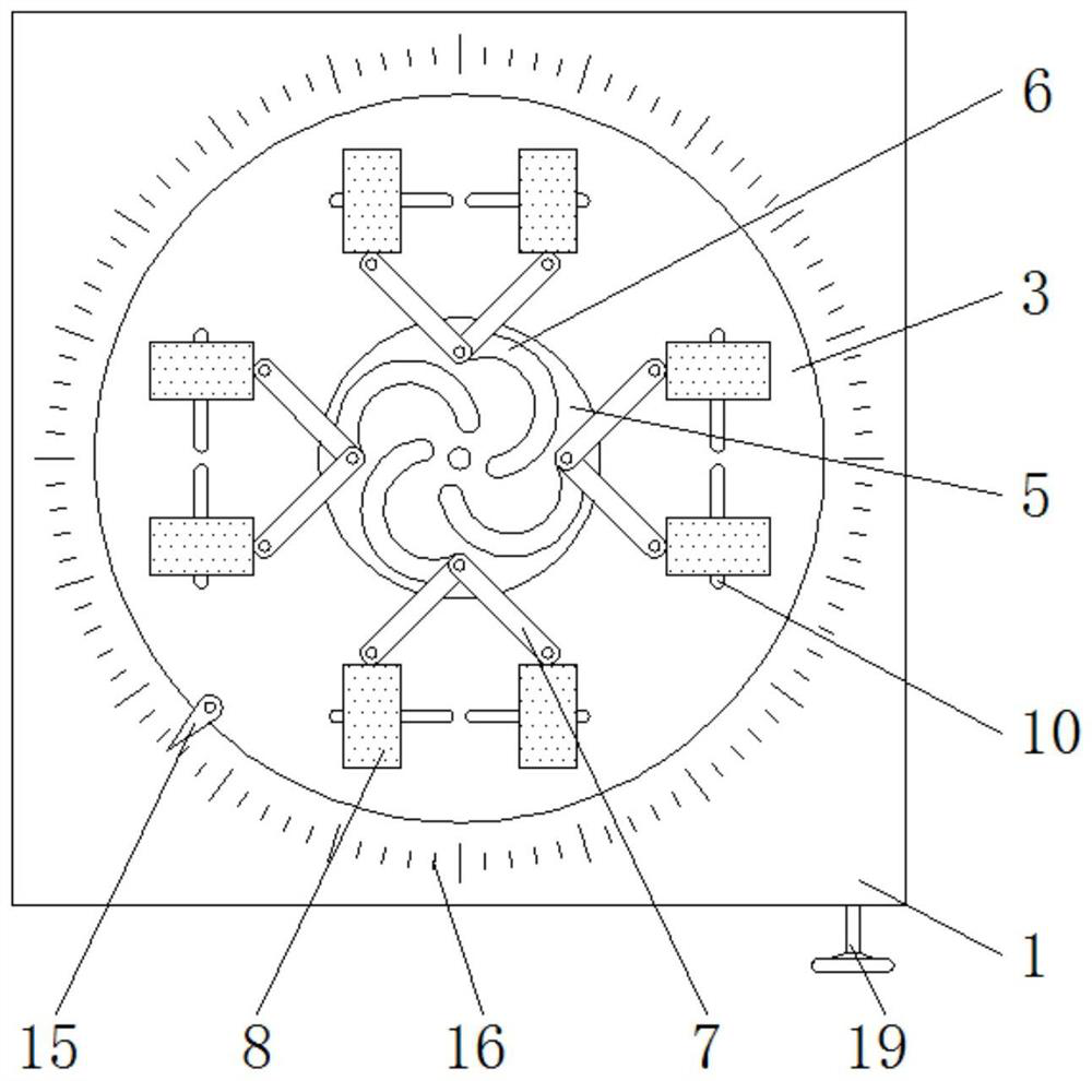
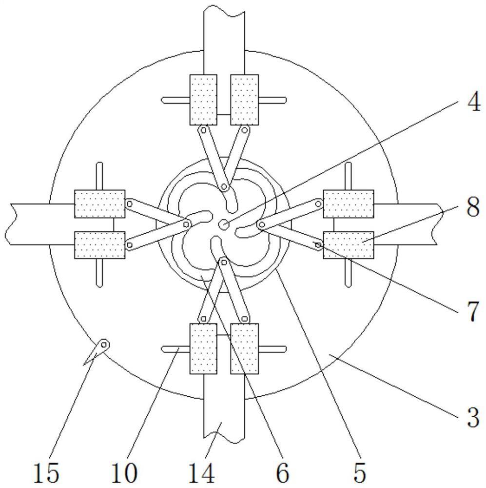
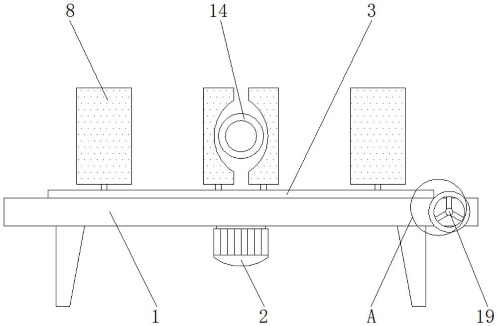
[0021] see Figure 1-5 , the present invention provides a technical solution: a multi-directional synchronous positioning mechanism for tubular workpieces for robot welding, including a processing table 1, a movable table 2, a motor 3, a motor shaft 4, a connecting plate 5, a movable groove 6, a guide rod 7, Clamp block 8, fixed block 9, limit groove 10, air bag 11, connecting cavity 12, air outlet hole 13, pipe fitting 14, index pin 15, angle line 16, worm wh...


PUM


Abstract

The invention discloses a tubular workpiece multi-direction synchronous positioning mechanism for robot welding. The mechanism comprises a machining table, a motor, a pipe fitting and an adjusting rod, a movable table is embedded in the upper end surface of the machining table, the top of the motor is rotationally connected with a motor shaft, a connecting plate is fixed to the top of the motor shaft, a movable groove is formed in the upper end surface of the connecting plate, a clamping block is movably installed at the other end of the guide rod, an air bag is pasted to the inner side of the clamping block, a connecting cavity is formed in the clamping block, an air outlet is reserved in the side surface of the clamping block, the pipe fitting is clamped by the inner side of the clamping block, a marking needle is arranged on the edge of the movable table, and the outer side of the movable table is sleeved with a worm gear. According to the tubular workpiece multi-direction synchronous positioning mechanism for robot welding, clamping of the pipe fitting can be automatically achieved, the phenomenon of deviation in the welding process can be avoided after clamping, meanwhile, synchronous clamping of multiple pipe fittings can be achieved through the same positioning mechanism, and then the machining efficiency is improved.

Description

technical field [0001] The invention relates to the technical field of robot welding, in particular to a multi-directional synchronous positioning mechanism for a tubular workpiece used for robot welding. Background technique [0002] With the continuous improvement of welding technology, robot welding has gradually replaced traditional manual welding. Compared with traditional welding technology, robot welding is more accurate and has higher welding efficiency. During the welding process, a positioning mechanism is needed to realize the positioning of the workpiece. According to different processing requirements, the shapes of workpieces processed are also different, and the welding of tubular workpieces also needs to be positioned. However, the existing tubular workpiece positioning mechanism still has the following disadvantages in the actual use process: [0003] Most of the traditional positioning mechanisms need to be manually adjusted to clamp the pipe fittings. Due t...

Claims


Application Information

Patent Timeline
Patent Type & Authority Applications(China)
IPC IPC(8): B23K37/00B23K37/04B23K37/047B23K101/06
Inventor 周太平刘玉海陈青伟巩振江
Owner 江苏欧朗汽车科技股份有限公司
Why Eureka
Try Eureka