Machining method of parallel membrane disc coupling

A processing method and coupling technology, applied in metal processing equipment, metal processing machinery parts, manufacturing tools, etc., can solve problems such as tools are prone to vibration, processing methods are not suitable, and affect the surface state of parts

Pending Publication Date: 2021-04-16
SHENYANG LIMING AERO-ENGINE GROUP CORPORATION
View PDF10 Cites 0 Cited by
  • Summary
  • Abstract
  • Description
  • Claims
  • Application Information

AI Technical Summary

Problems solved by technology

[0002] There is not much difference between the tool and the fixture used in traditional parts processing. If the tool is too long, it is easy to vibrate during processing, which will affect the surface state of the part; the processing method of radial positioning and axial compression is usually used during processing. For such special structural parts, traditional processing methods are not suitable

Method used

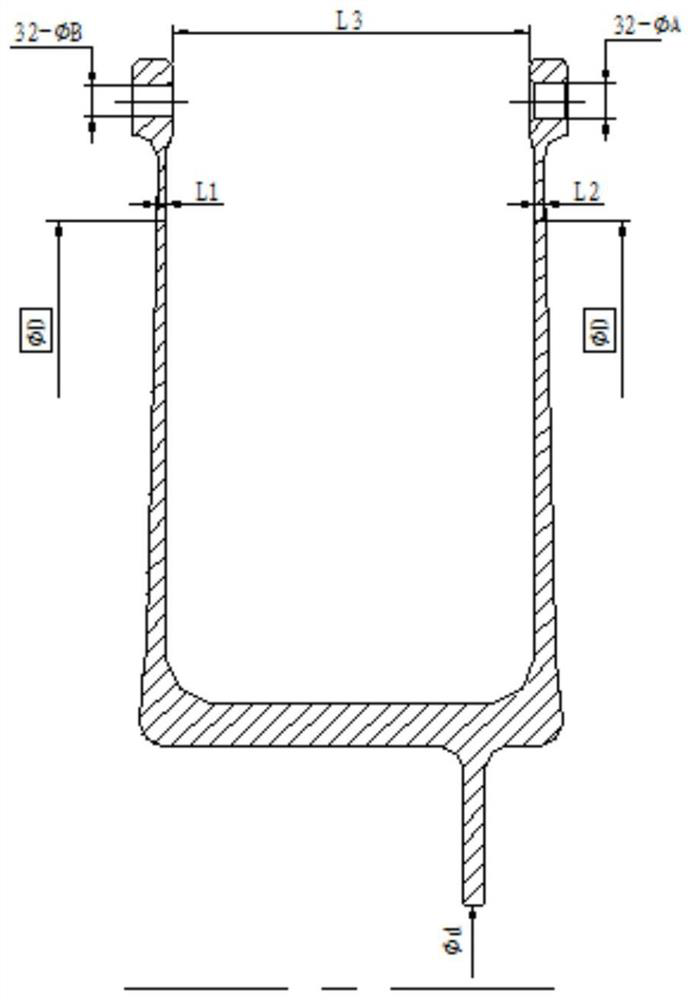

Image

  • Machining method of parallel membrane disc coupling
  • Machining method of parallel membrane disc coupling
  • Machining method of parallel membrane disc coupling

Examples


Embodiment 1

[0019] The invention provides a processing method of a parallel diaphragm disc coupling, which is characterized in that: the parallel diaphragm disc coupling is composed of two diaphragm discs and a central shaft, the axial thickness of the diaphragm discs is small, the radial overhang is long, and the two A deep cavity with a height of about 70mm is formed between two parallel diaphragm discs, and the length of the deep cavity exceeds 130mm. Traditional tools and clamping schemes are difficult to process, so a new processing method is created for processing; in the processing method of parallel diaphragm couplings, the tool Design: half of the length of the tool enters the deep cavity of the part for processing, and half of it is used for machine tool clamping to obtain sufficient tool rigidity, to ensure that the tool does not vibrate during the process, and to avoid the limitation of the machining stroke caused by the tool being too long; the CNC machining tool and the machin...

Embodiment 2

[0024] The lathe processing method of the parallel diaphragm coupling is described from four aspects: part structure, tool selection, fixture design, and parameter selection.

[0025] Part structure as attached figure 1 As shown, the wall thickness of the diaphragm of the parallel diaphragm coupling is 1.84mm, and the overhang is 145.5mm, which is a typical thin-walled structure. A deep cavity of 145.5mm deep and 73mm wide is formed in the middle of the parallel diaphragm disc.

[0026] The overall processing plan of the part is: processing the threaded hole → processing the deep cavity of the diaphragm → processing the outer surface of the diaphragm → processing the round hole

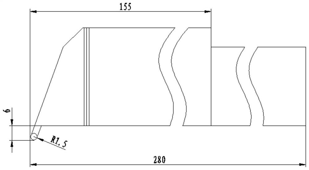
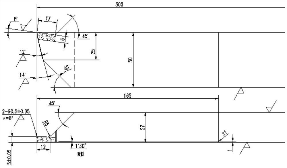
[0027] Tool selection is mainly based on reducing tool vibration. Figure 4 of knives. The length is 300mm, which meets the length requirement of deep cavity machining, but too long tool overhang will lead to insufficient tool rigidity and easy tool vibration during processing, so the tool thicknes...


PUM

PropertyMeasurementUnit
lengthaaaaaaaaaa

Abstract

The invention provides a machining method of a parallel membrane disc coupling. The machining method of the parallel membrane disc coupling comprises the following steps that a cutter of a special structure is selected, thickness of an overhanging part is increased, rigidity of the cutter is enhanced, a threaded hole is pre-processed in a final round hole part of a part, the part is clamped through the threaded hole, screws on the upper end surface and the lower end surface of the part is arranged for screwing due to particularity of the structure, and the machining rigidity of the part is guaranteed; a deep cavity overhanging tool long of the part is filled with foam, part machining vibration is absorbed, a shape follow-up filling block is manufactured, the part machining is supported, and part deformation is reduced; and cutter feeding and machining feeding are controlled, and the problem of large part deformation is solved. The machining method has the main defects that the time consumed by screw clamping is long, and a special wrench is needed for part clamping and disassembling. The method has the advantages that the problem that the cutter is prone to vibration during deep cavity machining is solved, machining reference is provided for thin-wall structural part machining, the design requirement is met, and the method has far-reaching significance on improvement of a new-generation engine manufacturing technology level.

Description

technical field [0001] The invention relates to the field of processing, in particular to a processing method for a parallel diaphragm coupling Background technique [0002] There is not much difference between the tool and the fixture used in traditional parts processing. If the tool is too long, it is easy to vibrate during processing, which will affect the surface state of the part; the processing method of radial positioning and axial compression is usually used during processing. For this special structural part, the traditional processing method is not suitable. Contents of the invention [0003] The purpose of the present invention is in order to overcome the above-mentioned problem, especially provides a kind of processing method of parallel diaphragm coupling. [0004] The invention provides a processing method of a parallel diaphragm disc coupling, which is characterized in that: the parallel diaphragm disc coupling is composed of two diaphragm discs and a centr...

Claims


Application Information

Patent Timeline
Patent Type & Authority Applications(China)
IPC IPC(8): B23P13/00B23P15/14B23Q3/00
Inventor 周闯崔建民李利军史前凯赵鹏飞
Owner SHENYANG LIMING AERO-ENGINE GROUP CORPORATION
Why Eureka
Try Eureka