
Battery energy-saving management system of new energy vehicle

A new energy vehicle and management system technology, applied in the field of battery energy saving management system of new energy vehicles, can solve the problems of reducing the use effect of the device, damage to the battery, time-consuming and laborious, etc., so as to increase the number of installations, improve practical performance, improve The effect of safety features

Inactive Publication Date: 2021-04-16
林玉珍
View PDF6 Cites 2 Cited by
  • Summary
  • Abstract
  • Description
  • Claims
  • Application Information

AI Technical Summary

Problems solved by technology

[0004] However, a new energy vehicle battery management can only fix the vehicle battery with bolts during use, so that when the operator needs to disassemble the battery, it will be extremely time-consuming and laborious, and may damage the battery in serious cases; and the traditional The traditional device can only install batteries of a certain height during use, which increases the limitations of battery installation; the traditional device cannot effectively implement layered installation during use, thereby reducing the number of batteries installed; and The heat dissipation effect of the traditional device is not obvious, which reduces the use effect of the device

Method used


Image

  • Battery energy-saving management system of new energy vehicle
  • Battery energy-saving management system of new energy vehicle
  • Battery energy-saving management system of new energy vehicle

Examples


Embodiment 1

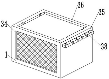
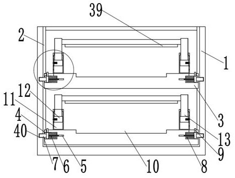
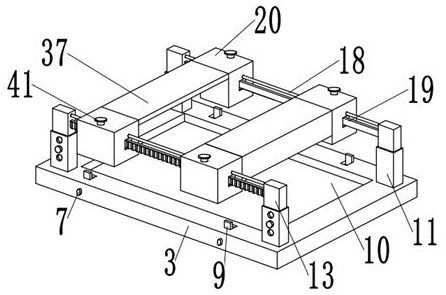
[0042] In summary, a battery energy-saving management system for a new energy vehicle provided by the present invention includes a housing 1, a No. There is a mounting plate 3 distributed in an up-and-down structure. There is a No. 1 mounting hole 4 on the outer walls of both sides of the mounting plate 3, and a jack 5 is opened at the center of the inner wall of the side where the No. 1 mounting holes 4 are far away from each other. The inside of the jack 5 The insertion rod 6 is inserted, and the outer wall of one end of the insertion rod 6 away from each other is welded with a No. 1 limit column 7 slidingly connected to the inside of the No. 1 installation hole 4, and the insertion rod 6 is located on the outer wall of the inner end of the No. 1 installation hole 4 A No. 1 spring 8 is socketed, and one end of the No. 1 spring 8 is welded on the outer wall of the side of the No. 1 limit post 7, and the other end of the No. 1 spring 8 away from the No. 1 limit post 7 is welded...


PUM


Abstract

The invention relates to the field of batteries of new energy vehicles, and aims to provide a battery energy-saving management system of a new energy vehicle, the battery energy-saving management system comprises a shell, first sliding grooves are formed in the inner walls of the two sides of the shell, mounting plates distributed in an up-down structure are slidably connected into the first sliding grooves, and first mounting holes are formed in the outer walls of the two sides of each mounting plate; inserting holes are formed in the centers of the inner walls of the sides, away from each other, of the first mounting holes, inserting rods are inserted into the inserting holes, and first limiting columns slidably connected into the first mounting holes are welded to the outer walls of the ends, away from each other, of the inserting rods. The system has the beneficial effects that through the arrangement of a gear, when an operator moves the device to a specified position under the action of a sliding rod, the operator can fix a push column through the mutual matching use of a threaded column, a lifting plate, a fixed limiting hole, a fixed limiting column and a stabilizing groove; due to the arrangement of the L-shaped baffle, the fixing effect of the device is more remarkable.

Description

technical field [0001] The invention relates to the battery field of new energy vehicles, in particular to a battery energy saving management system for new energy vehicles. Background technique [0002] Car battery is an essential part of the car. It can be divided into traditional lead-acid battery and maintenance-free battery. Because the battery uses lead-calcium alloy as the grid, the amount of water decomposition generated during charging is small, and the amount of water evaporation is also low. , In addition, the shell adopts a sealed structure, and the sulfuric acid gas released is very little, so it has the advantages of no need to add any liquid, butt-connected pile heads, and long power storage time compared with traditional batteries. [0003] Chinese Patent No. CN207504067U includes a management box body with a hollow structure inside. The inside of the management box body is equipped with evenly spaced spacer partitions. The interior of the spacer spacer is ho...

Claims


Application Information

Patent Timeline
Patent Type & Authority Applications(China)
IPC IPC(8): B60K1/04B60K1/00B60L58/26H01M50/249H01M50/264H01M50/267H01M10/613H01M10/625H01M10/6563
CPCY02T10/70Y02E60/10
Inventor 林玉珍
Owner 林玉珍
Learn More