
Piston pump set for brake system and control method thereof

A technology of a braking system and a control method, applied in the field of hydraulic braking, can solve the problems of affecting driving safety, difficult to determine the position where the piston stops, unable to ensure that the braking pressure of the piston pump can achieve the expected effect, etc., and achieves high structural strength. , to ensure the effect of stability

Active Publication Date: 2021-04-16
BYD CO LTD
View PDF4 Cites 3 Cited by
  • Summary
  • Abstract
  • Description
  • Claims
  • Application Information

AI Technical Summary

Problems solved by technology

However, after the previous movement of the piston pump is completed, it is difficult to determine the stop position of the piston, so when the next braking is required, the braking operation from the current stop position of the piston may not ensure the braking pressure generated by the piston pump Can achieve the expected effect, thereby affecting driving safety

Method used


Image

  • Piston pump set for brake system and control method thereof
  • Piston pump set for brake system and control method thereof
  • Piston pump set for brake system and control method thereof

Examples


Embodiment Construction

[0030] In order to make the object, technical solution and advantages of the present invention clearer, the present invention will be further described in detail below in conjunction with the accompanying drawings and embodiments. It should be understood that the specific embodiments described here are only used to explain the present invention, not to limit the present invention.

[0031] It should be noted that the terms "setting" and "connecting" should be understood in a broad sense, for example, they can be directly set and connected, or indirectly set and connected through a central component or a central structure.

[0032] In addition, if there are "longitudinal", "transverse", "length", "width", "thickness", "upper", "lower", "front", "rear", "left", " Terms such as "right", "vertical", "horizontal", "top", "bottom", "inner", "outer", etc. indicate the orientation or positional relationship, which are based on the orientation or positional relationship shown in the dr...


PUM


Abstract

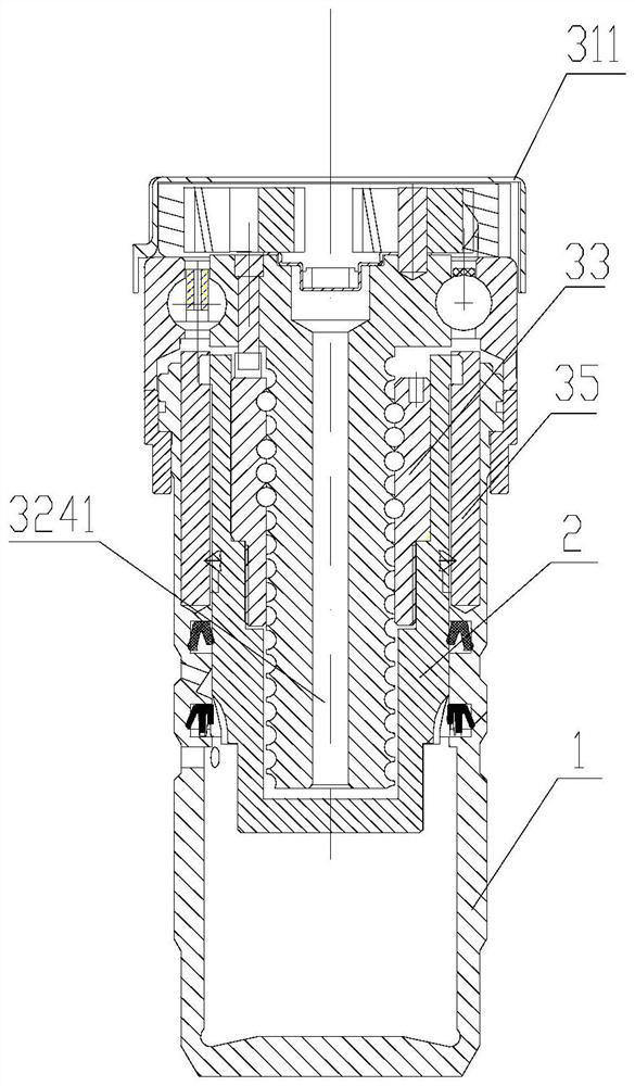
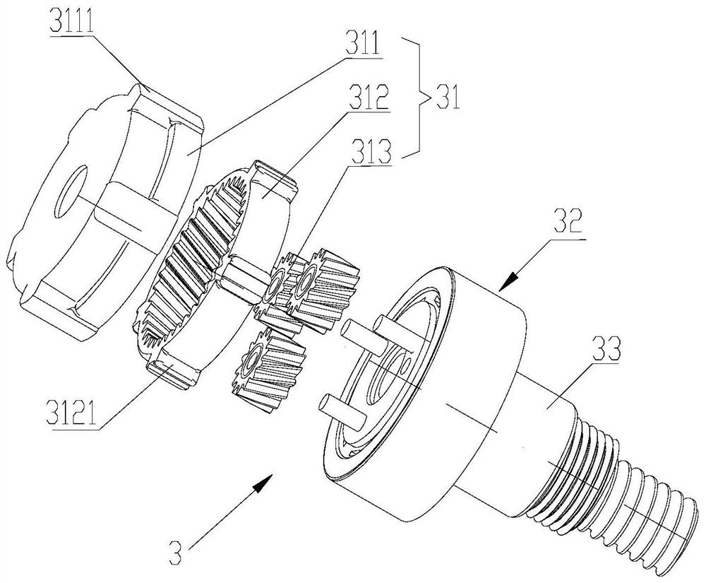
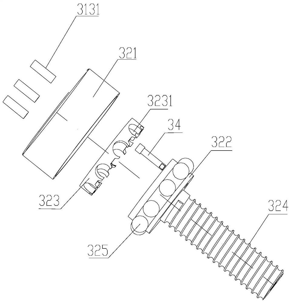
The invention is applicable to the technical field of hydraulic braking, and discloses a piston pump set for a brake system. The piston pump set comprises a piston, a pump body with a working cavity and a transmission mechanism for driving the piston to move in the working cavity, wherein the transmission mechanism comprises a lead screw transmission assembly, a driven part and a planetary gear assembly for transmitting power to the lead screw transmission assembly; the driven part is fixedly connected with the piston; the lead screw transmission assembly is used for driving the driven part to move relative to the working cavity; and a limiting component used for limiting movement of the driven part is arranged between the lead screw transmission assembly and the driven part. The invention further provides a control method for controlling the piston pump set for the brake system. According to the piston pump set for the brake system and the control method provided by the invention, the effect of pumping out high-pressure liquid can be better achieved, stable brake pressure is provided for the brake system, and the working stability is high.

Description

technical field [0001] The invention belongs to the technical field of hydraulic braking, and in particular relates to a piston pump group used in a braking system and a control method thereof. Background technique [0002] In hydraulic vehicle braking systems, piston pumps are used for service braking, and / or slip regulation. The piston pump generates the brake pressure for feeding the supplied brake fluid from the wheel brakes back to the wheel brakes after pressure reduction in order to increase the wheel brake pressure again, or for transferring the brake fluid to the main brake during slip adjustment. The direction of the moving cylinder is sent back. However, after the previous movement of the piston pump is completed, it is difficult to determine the stop position of the piston, so when the next braking is required, the braking operation from the current stop position of the piston may not ensure the braking pressure generated by the piston pump Can achieve the desi...

Claims


Application Information

Patent Timeline
Patent Type & Authority Applications(China)
IPC IPC(8): F04B49/14F04B53/00F04B53/14F04B53/22B60T11/16
CPCF04B49/14B60T11/16F04B9/02F04B17/03B60T13/745F16H2025/2087B60T13/20B60T17/221F04B17/00F04B49/00F04B2201/1201
Inventor 姚宇刚刘国杉苏东林刘静张楠
Owner BYD CO LTD
Learn More