Differential confocal fixed-surface interference target outer surface defect detection method and device

A defect detection and differential confocal technology, which is used in measurement devices, material analysis by optical means, instruments, etc., can solve the problems of difficult to achieve high precision of target pellets, large-scale automatic detection, etc., to improve efficiency and improve measurement. Accuracy, Guaranteed Measurement Accuracy and Effect of Measuring Focus Adjustment Efficiency

Active Publication Date: 2021-04-16
BEIJING INSTITUTE OF TECHNOLOGYGY
View PDF15 Cites 2 Cited by
  • Summary
  • Abstract
  • Description
  • Claims
  • Application Information

AI Technical Summary

Problems solved by technology

[0008] The purpose of the present invention is to solve the problem that the existing method is difficult to realize the high-precision and large-scale automatic detection of the defects on the outer surface of the target capsule, and proposes to use the differential confocal positioning technology to realize the accurate and fast automatic positioning of the target capsule and the camera in the interference optical path, and then effectively Guarantee the focusing accuracy and defect measurement accuracy of the outer surface, and provide the key technical basis and guarantee for rapid automatic inspection

Method used


Image

  • Differential confocal fixed-surface interference target outer surface defect detection method and device
  • Differential confocal fixed-surface interference target outer surface defect detection method and device
  • Differential confocal fixed-surface interference target outer surface defect detection method and device

Examples


Embodiment Construction

[0051] The present invention will be further described below in conjunction with drawings and embodiments.

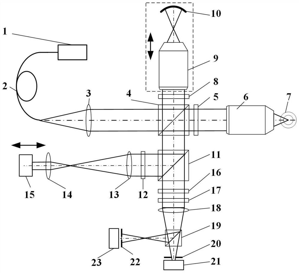
[0052] combine Figure 1-Figure 6 , a method and device for detecting defects on the outer surface of a differential confocal fixed-plane interference target, wherein the short-coherent linearly polarized light emitted by a short-coherent laser 1 is coupled into one end of an optical fiber 2, and the light emitted by the other end of the optical fiber 2 is collimated by a collimator The collimator 3 is parallel light, and the parallel light is divided into two paths by PBS4. The light beam passing through PBS4 passes through the first quarter-wave plate 5 and the measurement objective lens 6, and then converges at the spherical center of the target pellet 7 to be measured. The surface reflected beam passes through the first quarter-wave plate 5 and the measuring objective lens 6 again to form measuring light. The light beam reflected by PBS4 passes through the second q...


PUM


Abstract

The invention relates to a differential confocal fixed-plane interference target outer surface defect detection method and device, and belongs to the technical field of optical imaging and detection. According to the method, the zero crossing point of a differential confocal light intensity response curve is used for accurately positioning the axial positions of a target (a detected surface) and a camera (a detection surface), so that accurate and automatic focusing imaging of the outer surface is realized. A short coherent light source and a spherical reference mirror are adopted in an interference microscopic light path to generate an outer surface zero interference pattern; and then measuring outer surface defect distribution from the outer surface zero interferogram by using a phase-shifting interferometry. According to the invention, a more accurate adjustment judgment basis is provided for axial position adjustment of the target and the camera by using the accurate positioning characteristic of the differential confocal technology, so that the precision and efficiency of focusing and detection of the outer surface of the traditional interference microscopy method are effectively improved, and a necessary technical guarantee is provided for automatic detection. The invention provides a new technical approach for high-precision, high-efficiency and automatic detection of the outer surface defects of a large batch of targets.

Description

technical field [0001] The invention belongs to the technical field of optical imaging and detection, and is used for the precise detection of outer surface defects of target pills, which is the most core key device in inertial confinement fusion (ICF). Background technique [0002] Inertial confinement fusion (ICF) is not only an ideal technology for human beings to obtain clean energy in the future, but also provides strong support for the development of cutting-edge scientific research in condensed matter physics and astrophysics under extreme high temperature and high pressure conditions. At present, China, the United States, France, Russia, Japan and other countries have vigorously carried out ICF-related research. The ICF precisely focuses multiple high-energy lasers on a tiny hollow spherical target filled with DT fuel, and the shell of the target implodes instantly and uniformly compresses the DT fuel inside to a high-temperature and high-pressure state, thereby achi...

Claims


Application Information

Patent Timeline
Patent Type & Authority Applications(China)
IPC IPC(8): G01N21/892
Inventor 赵维谦杨帅王允邱丽荣
Owner BEIJING INSTITUTE OF TECHNOLOGYGY
Why Eureka
Try Eureka