Electrically controlled polarization beam splitting device with adjustable splitting ratio, and splitting ratio control method

A technology of polarization beam splitting and splitting ratio, which is applied in optics, nonlinear optics, instruments, etc., to achieve the effect of continuous change and precise dynamic adjustment

Pending Publication Date: 2021-04-16
NORTHWESTERN POLYTECHNICAL UNIV
View PDF6 Cites 1 Cited by
  • Summary
  • Abstract
  • Description
  • Claims
  • Application Information

AI Technical Summary

Problems solved by technology

[0003] Existing polarization beam splitters with adjustable polarization splitting ratio are also based on the electro-optical effect of liquid crystal materials to realize polarization splitting of light beams. Device and its working method", which discloses a polarizing beam splitter with an electrically controlled and adjustable polarization splitting ratio, which changes the

Method used


Image

  • Electrically controlled polarization beam splitting device with adjustable splitting ratio, and splitting ratio control method
  • Electrically controlled polarization beam splitting device with adjustable splitting ratio, and splitting ratio control method
  • Electrically controlled polarization beam splitting device with adjustable splitting ratio, and splitting ratio control method

Examples


Embodiment 1

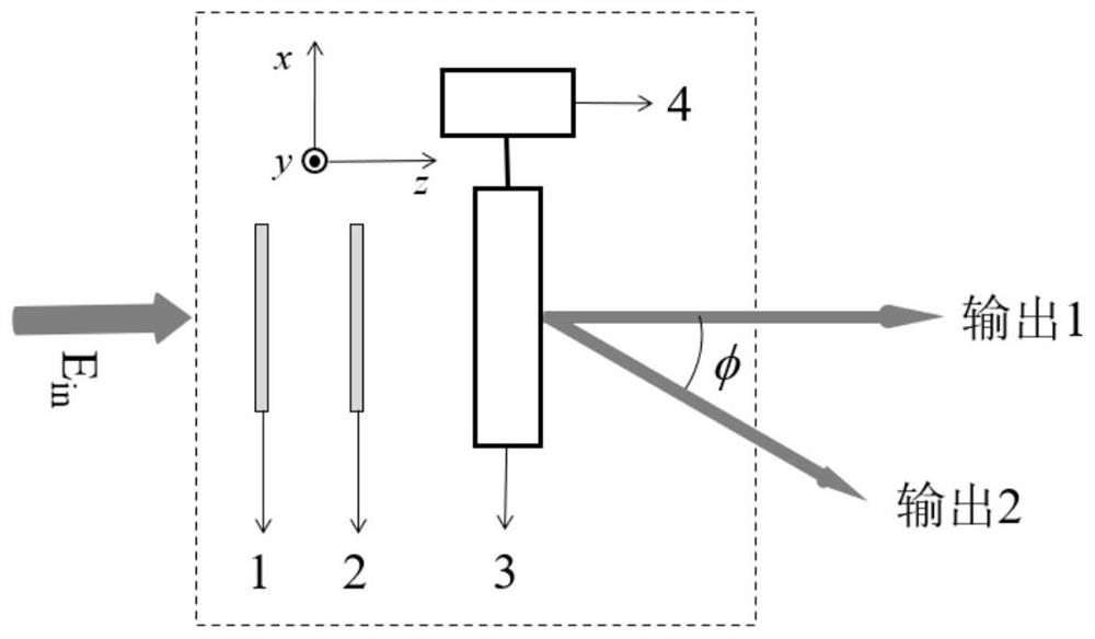
[0070] This embodiment provides an electronically controlled and adjustable polarization beam splitting device, which can directly decompose the incident light beam of any polarization state in a wide band into two beams of orthogonal circularly polarized light, that is, left-handed circularly polarized light and right-handed circularly polarized light. , and the energy splitting ratio of the two beams of circularly polarized light can be precisely and dynamically adjusted through external control voltage control. Such as figure 1 As shown, the polarizing beam splitting device with electrically controlled and adjustable splitting ratio includes a polarizer 1, an achromatic quarter-wave plate 2 and a liquid crystal polarization grating 3 that are arranged in sequence. Connected external control voltage driving device 4, wherein the angle between the polarizing direction of the polarizer and the fast axis of the achromatic quarter-wave plate is 45 degrees.

[0071] It should be...

Embodiment 2

[0089] This embodiment provides an electronically controlled and adjustable polarization beam splitting device, which can directly decompose an incident beam of any polarization state into two beams of linearly polarized light with the same polarization, and the beam splitting ratio of the two beams of linearly polarized light can be determined by External control voltage control realizes precise dynamic regulation. The method for realizing the same polarization beam splitting of any beam is the same as the method for realizing the orthogonal polarization beam splitting of any beam, but realizing the same polarization beam splitting needs to add an analyzer at the output end of the orthogonal polarization beam splitting device (embodiment 1) . Such as Figure 6 As shown, a polarizing beam splitting device with electrically controlled and adjustable splitting ratio, including a polarizer 1, an achromatic quarter-wave plate 2, a liquid crystal polarization grating 3 and an anal...


PUM


Abstract

The invention relates to an electronically controlled polarization beam splitting device with an adjustable splitting ratio, and a splitting ratio control method. The electronically controlled polarization beam splitting device comprises a light transmission light path composed of a polarizer, an achromatic quarter-wave plate and a liquid crystal polarization grating which are arranged in sequence, and an external control voltage driving device connected with the liquid crystal polarization grating. The included angle between the polarizing direction of the polarizer and the fast axis of the achromatic quarter-wave plate is 45 DEG, the liquid crystal polarization grating can realize polarization beam splitting, and the external control voltage driving device can change the birefringence of the liquid crystal polarization grating to realize continuous change of the splitting ratio. According to the invention, polarization wave division of any broadband incident light beam can be realized, and the splitting ratio can be continuously, accurately and dynamically adjusted through external control voltage.

Description

technical field [0001] The invention belongs to a polarization beam splitting device and method with adjustable splitting ratio, and relates to an electrically controlled and adjustable splitting ratio polarized beam splitting device and a method for controlling the splitting ratio. In particular, it relates to a polarization beam splitting method in which the splitting ratio of a wide-band arbitrary beam can be continuously and accurately adjusted dynamically through an external control voltage. It can be used in the field of optoelectronics to realize polarization splitting of a wide-band arbitrary beam. high efficiency. Background technique [0002] The beam splitter is one of the important components in the optical path system. The traditional beam splitting methods mainly rely on beam splitting prisms, polarizing beam splitting prisms, beam shifters, etc., but the splitting ratio of these beam splitting methods is fixed and cannot be adjusted, and the output beam The o...

Claims


Application Information

Patent Timeline
IPC IPC(8): G02F1/01G02F1/29G02F1/133
Inventor 李鹏毛塬刘圣赵建林
Owner NORTHWESTERN POLYTECHNICAL UNIV
Why Eureka
Try Eureka