Thermoelectric module and method for manufacturing thermoelectric module post
A thermoelectric module and terminal technology, which is applied in the manufacture/processing of thermoelectric devices, thermoelectric device components, circuits, etc., can solve problems such as condensation of thermoelectric modules, achieve a simple structure, and inhibit electrochemical migration.
- Summary
- Abstract
- Description
- Claims
- Application Information
AI Technical Summary
Problems solved by technology
Method used
Image
Examples
no. 1 approach
[0051]
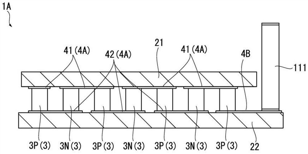
[0052] Such as figure 2 As shown, the thermoelectric module 1A has a pair of substrates 2 (upper substrate 21 and lower substrate 22), a plurality of thermoelectric elements 3 (p-type thermoelectric elements 3P and n-type thermoelectric elements 3N) arranged between these substrates 2, and These thermoelectric elements 3 are connected to the first electrode 4A (the upper electrode 41 and the lower electrode 42 ), the terminal 111 and the second electrode 4B.
[0053] The upper substrate 21 and the lower substrate 22 have a plate shape formed of an electrically insulating material. As an example, the upper substrate 21 and the lower substrate 22 are formed of ceramics. The upper substrate 21 faces the lower substrate 22 above and is arranged with a gap therebetween.
[0054] A plurality of thermoelectric elements 3 are arranged at intervals between the upper substrate 21 and the lower substrate 22 in the plane direction perpendicular to the thickness direction of ...
no. 2 approach
[0073]
[0074] Such as Figure 8 or Figure 9 As shown, the thermoelectric module 1B has a pair of substrates 2 (upper substrate 21 and lower substrate 22), a plurality of thermoelectric elements 3 (p-type thermoelectric elements 3P and n-type thermoelectric elements 3N) arranged between these substrates 2, and the The connection electrode 4C (electrode 4 ) to which these thermoelectric elements 3 are connected, the terminals 110 and 111 , and the terminal electrodes 4T to connect these terminals 110 and 111 to the thermoelectric elements 3 .
[0075] The upper substrate 21 and the lower substrate 22 have a plate shape formed of an electrically insulating material. The upper substrate 21 faces the lower substrate 22 above and is disposed with a gap therebetween. The upper substrate 21 and the lower substrate 22 are formed of ceramics as an example.
[0076] The upper substrate 21 and the lower substrate 22 are powder sintered bodies formed into a plate shape by sintering...
no. 3 approach
[0094]
[0095] Such as Figure 12 or Figure 13 As shown, the thermoelectric module 1C has: a pair of substrates 2 (upper substrate 21 and lower substrate 22); a plurality of thermoelectric elements 3 (p-type thermoelectric elements 3P and n-type thermoelectric elements 3N) arranged between these substrates 2; Connection electrode 4C (electrode 4 ) connecting these thermoelectric elements 3 ; heating thermoelectric element 3H; terminals 110 , 111 ; end electrodes 4T connecting these terminals 110 , 111 and thermoelectric elements 3 .
[0096] The upper substrate 21 and the lower substrate 22 have a plate shape formed of an electrically insulating material. The upper substrate 21 faces the lower substrate 22 above and is disposed with a gap therebetween. As an example, the upper substrate 21 and the lower substrate 22 are formed of ceramics.
[0097] Such as Figure 12 As shown, a plurality of thermoelectric elements 3 are arranged in a grid pattern at intervals between ...
PUM
 Abstract
Description
Claims
Application Information
 - R&D
- Intellectual Property
- Life Sciences
- Materials
- Tech Scout
- Unparalleled Data Quality
- Higher Quality Content
- 60% Fewer Hallucinations
Browse by: Latest US Patents, China's latest patents, Technical Efficacy Thesaurus, Application Domain, Technology Topic, Popular Technical Reports.
© 2025 PatSnap. All rights reserved.Legal|Privacy policy|Modern Slavery Act Transparency Statement|Sitemap|About US| Contact US: help@patsnap.com


