Agricultural soil turning device

An agricultural and winding device technology, which is applied in the fields of agriculture, agricultural machinery and implements, applications, etc., can solve the problems such as the inability of the wheel to move forward, the insufficient anti-skid effect of the anti-skid wheel, and the reduction of the soil turning efficiency, so as to improve the degree of adaptability and the scope of application. , the effect of reducing costs

Active Publication Date: 2021-04-20
威海大风车农业科技股份有限公司
View PDF6 Cites 0 Cited by
  • Summary
  • Abstract
  • Description
  • Claims
  • Application Information

AI Technical Summary

Problems solved by technology

However, the anti-skid effect of anti-skid wheels alone is not enough, and it can only be used on dry soil surfaces. When the soil is wet and muddy, the wheels of the soil-turning device are likely to sink into the soil and cannot move forward, reducing the efficiency of soil-turning.

Method used


Image

  • Agricultural soil turning device
  • Agricultural soil turning device
  • Agricultural soil turning device

Examples


Embodiment 1

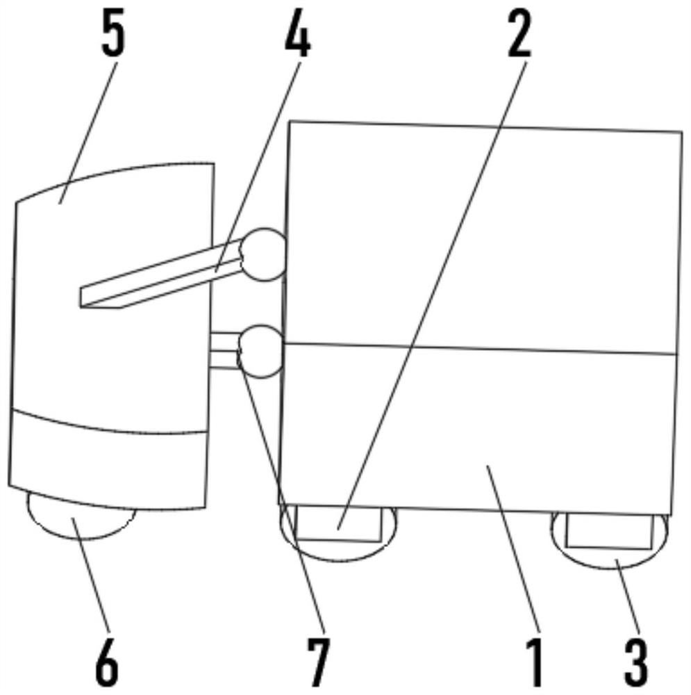
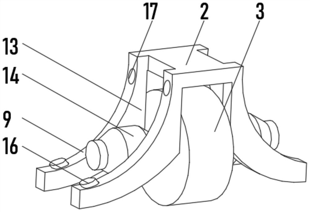
[0031] see Figure 1-3, the present invention provides a technical solution: an agricultural tillage device, comprising a fuselage 1, the bottom of the fuselage 1 is uniformly installed with a roller 3 through the mounting frame 2, and one end of the fuselage 1 is connected with a tiller through a drive rod 4 5. A soil-turning knife 6 is evenly installed on the bottom of the soil-turning frame 5, and the soil-turning knife 6 is connected to the fuselage 1 in rotation through the limit rod 7 once. Both sides of the mounting frame 2 are fixedly connected with a vertical plate 8. 8 The side away from the installation frame 2 is rotationally connected with a buffer plate 9, and the top of the buffer plate 9 is connected with the vertical plate 8 by adjusting the elastic plate 10

[0032] When in use, start the driving rod 4 to move the tiller 5 downward until the tiller 6 moves to the inside of the soil, and the driving body 1 drives the roller 3 to rotate forward, and the tiller ...

Embodiment 2

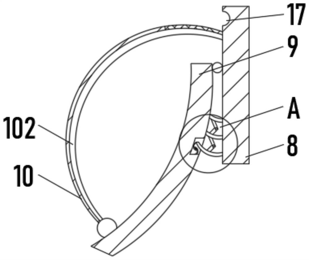
[0034] see Figure 1-5 , the present invention provides a technical solution: on the basis of Embodiment 1, the adjustable elastic plate 10 includes an arc spring plate 101, the end of the arc spring plate 101 close to the vertical plate 8 is a rigid plate, and the bottom of the arc spring plate 101 An adjustment groove 102 is provided, and an elastic short plate 103 is evenly installed between the two sides of the inner wall of the adjustment groove 102. One end of the elastic short plate 103 is fixedly connected with a pull plate 104, and the bottoms of the adjustment groove 102 and the elastic short plate 103 are provided with The pull plate 104 is matched with the slot 105 .

[0035] When in use, pull the pull plate 104 down along the adjustment groove 102, the pull plate 104 drives the elastic short plate 103 to move down to the bottom end of the adjustment groove 102, press the pull plate 104 until the pull plate 104 snaps into the inside of the slot 105 Fix, move diffe...

Embodiment 3

[0037] see Figure 1-5 , the present invention provides a technical solution: on the basis of Embodiment 1, the bottom of the buffer plate 9 is connected to the vertical plate 8 through the winding device 11, and the end of the winding device 11 away from the vertical plate 8 is equipped with a locking device 12.

[0038] Rewinding device 11 comprises rewinding push plate 111, and rewinding push plate 111 is an elastic plate and rewinding push plate 111 is evenly installed in the position between vertical plate 8 and buffer plate 9, and between rewinding push plate 111 passes first The rotating plate 112 is rotatably connected to the second rotating plate 113 .

[0039] The locking device 12 includes an upper arc plate 121, the top of the upper arc plate 121 is fixedly connected with the rolling push plate 111, and the buffer plate 9 is provided with a locking groove 122 near the upper arc plate 121, and the inside bottom of the locking groove 122 is fixed. The lower arc plat...


PUM


Abstract

The invention discloses an agricultural soil turning device, and relates to the technical field of agricultural equipment. The agricultural soil turning device comprises a machine body, rollers are uniformly mounted at the bottom of the machine body through a mounting frame, one end of the machine body is connected with a soil turning frame through a driving rod, and soil turning knives are uniformly mounted at the bottom of the soil turning frame; one sides of the soil turning knives are rotatably connected with the machine body through a limiting rod, vertical plates are fixedly connected to the two sides of the mounting frame, buffer plates are rotatably connected to the sides, away from the mounting frame, of the vertical plates, the tops of the buffer plates are connected with the vertical plates through adjusting elastic plates, and the bottoms of the buffer plates are connected with the vertical plates through winding devices; and clamping devices are mounted at the ends, away from the vertical plates, of the winding devices. According to the agricultural soil turning device, the anti-skid capacity of the soil turning device can be greatly improved, the soil turning device can normally move forwards under the condition that soil is humid and muddy, normal work of the soil turning device is guaranteed, and the application range of the soil turning device is widened.

Description

technical field [0001] The invention relates to the technical field of agricultural equipment, in particular to an agricultural soil turning device. Background technique [0002] In agricultural production, the soil on the ground surface needs to be loosened before planting crops, which not only loosens the soil to facilitate the respiration of plant roots, but also kills the pests in the soil. [0003] Chinese invention CN106134539A discloses a manual tiller for farming, including a front steering wheel, a loosening knife, a drive shaft, an engine, and a rear anti-skid wheel. The front steering wheel is provided with a hub, and the inside of the hub A drive shaft is provided, the rear anti-skid wheel is provided on the side of the drive shaft, a steel ball ring is provided on the side of the rear anti-skid wheel, a coupling is provided in front of the rigid ball ring, and the coupling A water tank is arranged in front of the water tank, a pull rod is arranged above the wat...

Claims


Application Information

Patent Timeline
Patent Type & Authority Applications(China)
IPC IPC(8): A01B33/00A01B33/08
Inventor 安田立
Owner 威海大风车农业科技股份有限公司
Why Eureka
Try Eureka