Round steel plate stamping equipment for steel processing

A kind of stamping equipment and circular technology, which is applied in the field of circular steel plate stamping equipment, can solve the problems of low automation, long time consumption, slow transportation speed, etc., and achieve the goal of improving processing efficiency, saving stamping and feeding time, and easy stamping Effect

Active Publication Date: 2021-04-20
温岭市浙江下张钢铁市场有限公司
View PDF8 Cites 1 Cited by
  • Summary
  • Abstract
  • Description
  • Claims
  • Application Information

AI Technical Summary

Problems solved by technology

[0004] In order to overcome the shortcomings of slow steel plate transportation, long processing time, low efficiency and low degree of automation, the technical problem to be solved is to provide a steel plate with fast transportation speed, short processing time, high efficiency, and more Automated, circular material stamping equipment for steel processing that reduces reliance on manual labor

Method used


Image

  • Round steel plate stamping equipment for steel processing
  • Round steel plate stamping equipment for steel processing
  • Round steel plate stamping equipment for steel processing

Examples


Embodiment 1

[0066] A circular steel sheet stamping equipment for steel processing, such as figure 1 As shown, it includes an organic base 1, a machine foot 2, a stamping mechanism 3 and a feeding mechanism 4. Feeding mechanism4.

[0067] When people need to stamp the material, the material is first placed on the feeding mechanism 4, then the stamping mechanism 3 is started to stamp the circular material, and after the stamping is completed, the stamping mechanism 3 is closed.
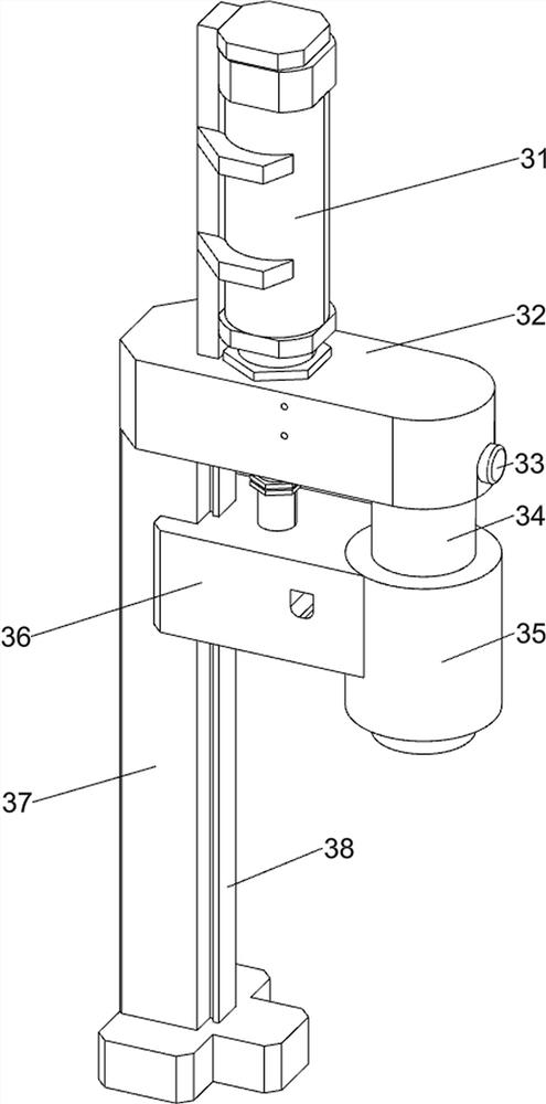
Embodiment 2

[0069] On the basis of Example 1, such as figure 2As shown, the stamping mechanism 3 includes a cylinder 31, a machine head 32, a positioning pin 33, a main shaft 34, a die 35, a slider 36, a support column 37 and a first guide rail 38, and the left side of the base 1 is provided with a support column 37 , the right side of the support column 37 is provided with a first guide rail 38, the support column 37 is provided with a head 32, the top of the head 32 is provided with a cylinder 31, the bottom of the head 32 is provided with a main shaft 34, and between the main shaft 34 and the head 32 Locating pin 33, main shaft 34 is slidingly connected with die 35, the left side of die 35 is provided with slide block 36, slide block 36 is connected with slide type between the first guide rail 38, and slide block 36 top is connected with cylinder 31 bottoms.

[0070] When the material is located on the lower side of the die 35, start the cylinder 31, and the stretching motion of the c...
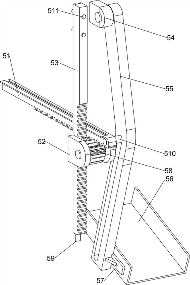
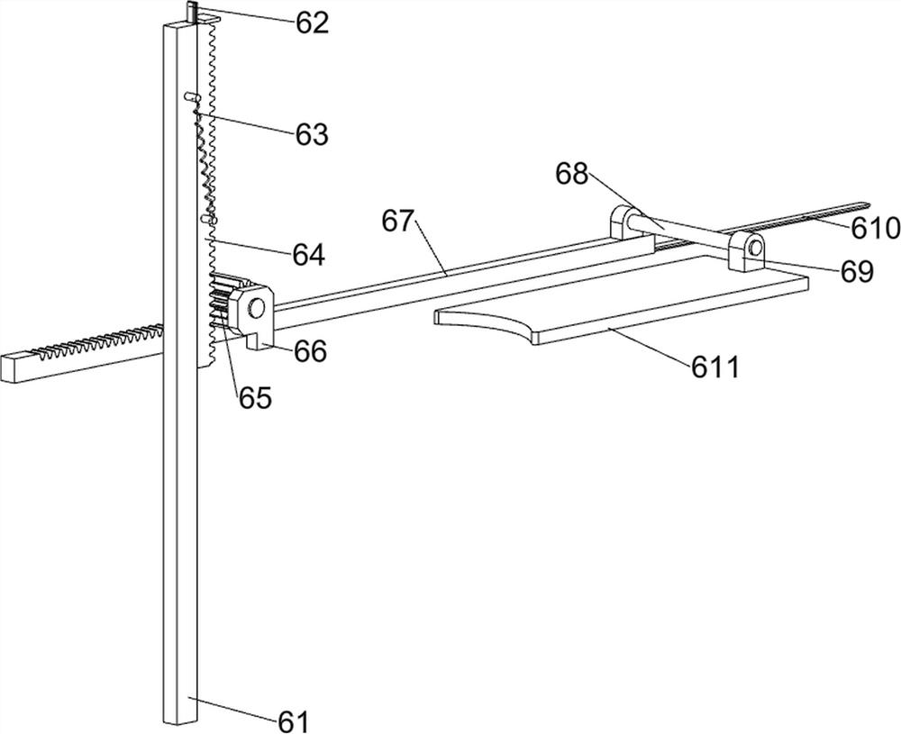
Embodiment 3

[0072] On the basis of Example 2, such as Figure 3 to Figure 7 As shown, the feed mechanism 4 includes a feed frame 41, a limit block 42 and a material storage box 43. The base 1 is provided with a feed frame 41, and the front portion of the feed frame 41 has a small opening. Bottom left and right sides are all provided with stop block 42, and stop block 42 is all positioned at the small opening front side, is provided with stock box 43 on the feed frame 41, and stock box 43 bottom front and rear sides all have push-out mouth.

[0073] When the material is positioned at the lower side of the die 35, the cylinder 31 is activated, and the stretching motion of the cylinder 31 drives the slider 36 to move downward. People place the material in the material storage box 43 and manually push the material to move forward. The material storage box 43 can A lot of materials are stored at one time, which saves the time for people to carry the materials. When the materials hit the limit ...


PUM


Abstract

The invention relates to stamping equipment, in particular to round steel plate stamping equipment for steel machining. The technical problem to be solved is to provide round material stamping equipment for steel machining, which is high in steel plate conveying speed, short in machining process time, high in efficiency, more automatic and capable of reducing dependence on manpower. According to the technical implementation scheme of the invention, the round steel plate stamping equipment for steel machining comprises machine legs, a stamping mechanism and a feeding mechanism, wherein the machine legs are arranged on the periphery of a machine base; the stamping mechanism is arranged on one side of the machine base; and the feeding mechanism is arranged on the machine base. Through cooperation of the stamping mechanism and the feeding mechanism, automatic feeding of materials can be achieved, the materials can be stamped easily, and stamping and feeding time is saved.

Description

technical field [0001] The invention relates to stamping equipment, in particular to a circular steel plate stamping equipment used for steel processing. Background technique [0002] The emergence of steel has strongly promoted the development of social production. With the development of society, steel has played an important role in many aspects. Especially in industrial development, steel has inestimable value. Steel can be processed into many shapes. However, many steps in the steel processing process still need to rely on manual labor, and there are a series of shortcomings, such as limited human strength, slow steel plate transportation speed, large steel volume, long processing time, low efficiency, low degree of automation, and The processing of steel will release toxic substances, which will damage human health. [0003] Therefore, a circular material stamping equipment for steel processing has been developed that has faster steel plate transportation speed, short...

Claims


Application Information

Patent Timeline
Patent Type & Authority Applications(China)
IPC IPC(8): B21D22/02B21D45/08B21D43/02B21D43/24B21D43/22B21D43/20B21D43/28
CPCY02P70/10
Inventor 刘翔
Owner 温岭市浙江下张钢铁市场有限公司
Why Eureka
Try Eureka