
Winding device with cutting structure for chemical fiber braid

A chemical fiber and plate rolling technology is applied in the field of chemical fiber webbing processing equipment, which can solve the problems of wasting chemical fiber webbing cutting time, inability to cut chemical fiber webbing, inconvenient to remove the winding roller, etc. Simple and convenient effects

Pending Publication Date: 2021-04-20
吴江保利化纺有限公司
View PDF0 Cites 1 Cited by
  • Summary
  • Abstract
  • Description
  • Claims
  • Application Information

AI Technical Summary

Problems solved by technology

[0003] During the use of the existing retracting device for chemical fiber webbing, it cannot cut the wound chemical fiber webbing by itself in time, and needs the help of external cutting equipment, which wastes the time for cutting the chemical fiber webbing, and the entire retraction after winding The winding roller is inconvenient to take off, resulting in inconvenient operation to replace with a new winding roller, which cannot satisfy people's needs well. In view of the above situation, the inventor made technical innovation on the basis of the existing winding device for chemical fiber webbing , proposed a retracting device with cutting structure for chemical fiber webbing

Method used

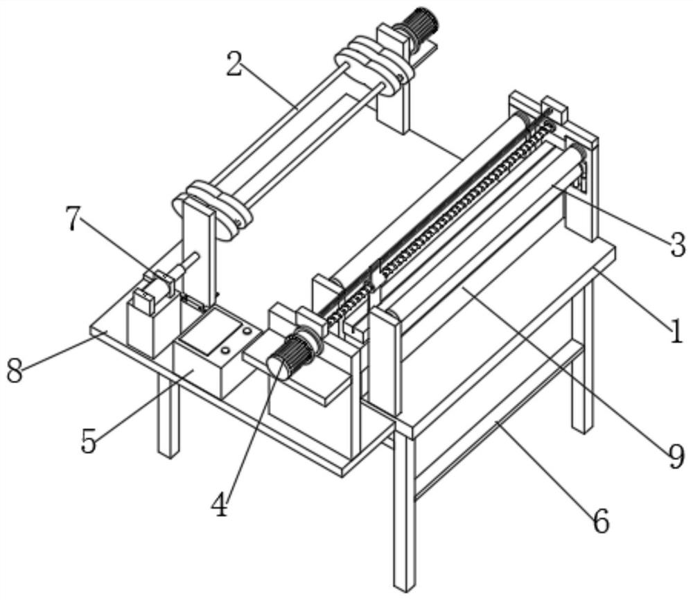
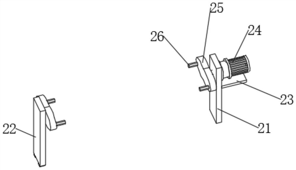
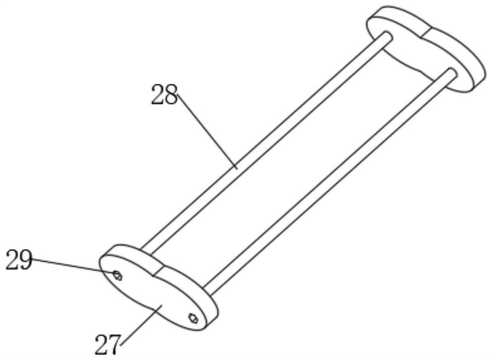

Image

  • Winding device with cutting structure for chemical fiber braid
  • Winding device with cutting structure for chemical fiber braid
  • Winding device with cutting structure for chemical fiber braid

Examples


Embodiment Construction

[0034] In order to make the technical means, creative features, goals and effects achieved by the present invention easy to understand, the present invention will be further described below in conjunction with specific embodiments.

[0035] In the description of the present invention, it should be noted that the terms "upper", "lower", "inner", "outer", "front end", "rear end", "both ends", "one end", "another end" The orientation or positional relationship indicated by etc. is based on the orientation or positional relationship shown in the drawings, and is only for the convenience of describing the present invention and simplifying the description, rather than indicating or implying that the referred device or element must have a specific orientation, use a specific Azimuth configuration and operation, therefore, should not be construed as limiting the invention. In addition, the terms "first" and "second" are used for descriptive purposes only, and should not be understood ...


PUM


Abstract

The invention discloses a winding device with a cutting structure for a chemical fiber braid. The winding device comprises a table plate, a supporting frame, a winding mechanism, two sets of pressing mechanisms, a cutting assembly, a supporting mechanism, a mounting plate, a pushing mechanism, and a control box, wherein the supporting frame is fixedly arranged at the lower end of the table plate, the winding mechanism is fixedly arranged on the front portion of the upper end of the table plate, the two sets of pressing mechanisms are fixedly arranged on the rear portion of the upper end of the table plate, the cutting assembly is arranged above the two sets of pressing mechanisms, the supporting mechanism is arranged between the two sets of pressing mechanisms, the mounting plate is fixedly arranged at the left end of the table plate, the pushing mechanism and the control box are fixedly arranged at the upper end of the mounting plate, the pushing mechanism is composed of a base and a second hydraulic cylinder fixedly arranged at the upper end of the base, and the winding mechanism is composed of a driving mechanism and a winding assembly. According to the winding device with the cutting structure for the chemical fiber braid, the winding assembly is conveniently and rapidly mounted and dismounted, the winding assembly is conveniently replaced, operation is easy, convenient and fast, automatic cutting can be carried out without the help of external cutting equipment, and the winding device has wide application prospects and is suitable for popularization.

Description

technical field [0001] The invention relates to the field of chemical fiber webbing processing equipment, in particular to a retracting device with a cutting structure for the chemical fiber webbing. Background technique [0002] Ribbon is a kind of narrow fabric or tubular fabric made of various yarns, while chemical fiber ribbon refers to a kind of ribbon processed from chemical fibers, which is widely used in clothing, shoe materials, luggage, industry, agriculture , military supplies, transportation and other fields, with the continuous development of textile production technology, the continuous improvement of ribbon production technology has been promoted. [0003] During the use of the existing retracting device for chemical fiber webbing, it cannot cut the wound chemical fiber webbing by itself in time, and needs the help of external cutting equipment, which wastes the time for cutting the chemical fiber webbing, and the entire retraction after winding The winding r...

Claims


Application Information

Patent Timeline
Patent Type & Authority Applications(China)
IPC IPC(8): B65H23/16B65H18/02B65H18/10D06H7/02
Inventor 黄伟东
Owner 吴江保利化纺有限公司
Learn More