Catalytic conversion method and device for prolific production of low-carbon olefins

A technology for low-carbon olefins and catalysts, which is applied in the field of catalytic conversion and devices for prolific low-carbon olefins. It can solve the problems of no coupling optimization and further improvement in yield, and achieve the reduction of thermal cracking reactions, reduction of hydrogen transfer reactions, and improvement of Yield effect

Active Publication Date: 2022-02-08
CHINA PETROLEUM & CHEM CORP +1
View PDF16 Cites 0 Cited by
  • Summary
  • Abstract
  • Description
  • Claims
  • Application Information

AI Technical Summary

Problems solved by technology

[0009] The above technologies promote the conversion of heavy hydrocarbon feedstocks and the selectivity of low-carbon olefins by adjusting the catalyst formulation and adopting a combined reactor form combining a riser and a fluidized bed, but there is no coupling between catalysts of different formulations and feedstock oils of different properties optimization, the yield of ethylene and propylene needs to be further improved

Method used


Image

  • Catalytic conversion method and device for prolific production of low-carbon olefins
  • Catalytic conversion method and device for prolific production of low-carbon olefins
  • Catalytic conversion method and device for prolific production of low-carbon olefins

Examples


Embodiment 1

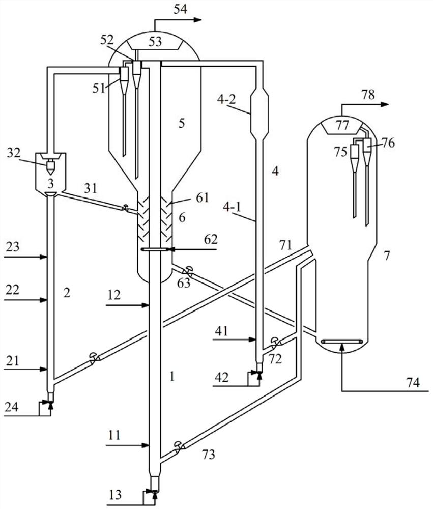
[0062] The tests were carried out on a medium-scale test rig. The plant consists of three riser reactors and one fluidized bed reactor. The inner diameter of the first riser reactor 1 is 16mm, and the length is 3200mm. The inner diameter of the second riser reactor 2 is 16mm, and the height is 3000mm. The inner diameter of the fluidized bed reactor 3 is 64mm, and the height is 500mm. Reactor 4 has an inner diameter of 16 mm and a height of 2800 mm. Fresh raw oil is introduced into the bottom of the first riser reactor 1, contacts and reacts with the regenerated catalyst from the regenerator 7, and the reacted oil mixture is separated by a cyclone separator; cracked heavy oil is introduced into the bottom of the second riser reactor 2 , the regenerated catalyst CAT from the regenerator 7 contacts and reacts, and then contacts and reacts with the C4 hydrocarbon introduced into the middle of the second lifting reactor 2, and the resulting oil mixture is introduced into the fluid...

Embodiment 2

[0064] According to the method of embodiment 1, difference is that the 3rd riser reactor 4 is made up of two reaction zones, wherein the inner diameter of the first reaction zone is 16mm, and the height is 2000mm, and the inner diameter of the second reaction zone is 30mm, and the height is 2000mm. 800mm. The reaction conditions and results are shown in Table 3.

Embodiment 3

[0066] According to the method of embodiment 2, the difference is that in addition to introducing the C4 fraction obtained by fractionation into the second riser reactor 2, the light gasoline fraction obtained by fractionation (distillation range 40 ~ 80 ° C, olefin content is 65% by weight ) is introduced into the second riser reactor 2, and the mass ratio of the cracked heavy oil, C4 hydrocarbons, light gasoline fraction and fresh raw oil is 0.05:0.05:0.05:1. The reaction conditions and results are shown in Table 3.


PUM

PropertyMeasurementUnit
densityaaaaaaaaaa
pore sizeaaaaaaaaaa
densityaaaaaaaaaa

Abstract

A catalytic conversion method and device for prolific production of low-carbon olefins, comprising: the first hydrocarbon feedstock and the catalyst from the regenerator are contacted and reacted in the first riser reactor, and the heavy hydrocarbon feedstock, the second hydrocarbon feedstock and the The catalyst from the regenerator is contacted and reacted in the second riser reactor, and the reacted oil mixture is introduced into the fluidized bed reactor to continue the reaction. The contact reaction is carried out in the first reaction zone and the second reaction zone, and the reacted oil mixture is separated by the separation device, and the catalyst is introduced into the stripper for stripping. Heavy hydrocarbons are introduced into the bottom of the second riser reactor, and the third hydrocarbon feedstock is selected from distillate oils with a distillation range of 180°C to 360°C, preferably distillate oils with a distillation range of 200°C to 340°C. The method of the invention can significantly increase the yield of ethylene and propylene.

Description

technical field [0001] The invention relates to a catalytic conversion method and device for prolific production of low-carbon olefins. Background technique [0002] In recent years, with the continuous development of the chemical industry, the demand for low-carbon olefins such as ethylene and propylene has shown a rapid growth trend, and there is a large gap in the low-carbon olefins market. At present, the methods for producing low-carbon olefins mainly include steam cracking technology, catalytic cracking technology, propane dehydrogenation to propylene technology, and coal-to-methanol to olefins technology. Among them, steam cracking technology is the main source of low-carbon olefins. The ethylene produced by it accounts for more than 95% of the total ethylene output, propylene accounts for about 61% of the total propylene output, and the propylene produced by catalytic cracking technology accounts for about 34% of the total propylene output. . As steam cracking adop...

Claims


Application Information

Patent Timeline
Patent Type & Authority Patents(China)
IPC IPC(8): C10G55/00C10G3/00C07C4/06C07C11/04C07C11/06
CPCY02P20/52Y02P20/584
Inventor 马文明朱根权杨超
Owner CHINA PETROLEUM & CHEM CORP
Why Eureka
Try Eureka