
Heating crucible for vacuum evaporation and vacuum evaporation device

A crucible and vacuum technology is applied in the fields of heating crucibles for vacuum evaporation and vacuum evaporation devices, which can solve problems such as deterioration, inconvenient installation and maintenance, and small outlet, so as to prevent decomposition and deterioration, facilitate use and maintenance, and prevent cooling the effect of condensation

Active Publication Date: 2021-06-29
苏州盟萤电子科技有限公司
View PDF8 Cites 0 Cited by
  • Summary
  • Abstract
  • Description
  • Claims
  • Application Information

AI Technical Summary

Problems solved by technology

[0003] Generally, the vacuum evaporation device is only equipped with a heating device on the outer periphery of the crucible. Therefore, the temperature at the outlet of the lower part of the crucible is inconsistent with that at the outlet of the upper part. Generally, the temperature at the outlet of the crucible is relatively low, so the vaporized evaporation material is easy to condense into a solid at the outlet, making the outlet If the size becomes smaller, the amount of sprayed evaporation material will decrease, which will seriously affect the uniformity of film thickness, and the solid will continue to accumulate, and the outlet will be easily blocked, which will not only have a greater impact on product quality, but also affect production efficiency and the convenience of using the evaporation device
In view of the above technical problems, the existing solution is to install a heating device at the position of the crucible cover to heat the crucible cover and the nozzle. On the one hand, the heating device directly transfers heat to the crucible cover and the nozzle through heat conduction, so the heating temperature cannot be controlled stably, and the local temperature of the crucible cover and the nozzle is likely to be too high, resulting in the decomposition or deterioration of the evaporation material

Method used


Image

  • Heating crucible for vacuum evaporation and vacuum evaporation device
  • Heating crucible for vacuum evaporation and vacuum evaporation device
  • Heating crucible for vacuum evaporation and vacuum evaporation device

Examples


Embodiment Construction

[0032] In order to make the object, technical solution and advantages of the present invention clearer, the present invention will be described in detail below in conjunction with the accompanying drawings and specific embodiments.

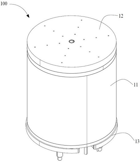
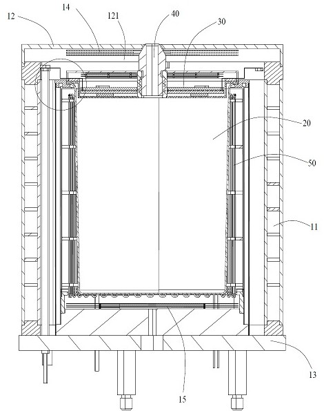
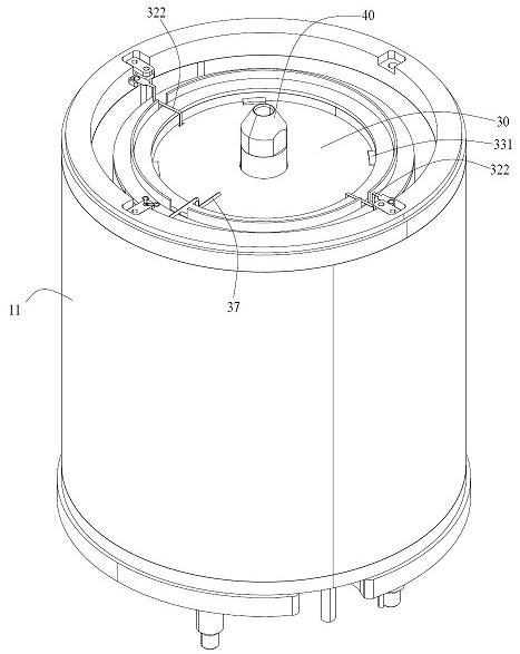
[0033] Please refer to Figure 1 to Figure 3 As shown, the present invention provides a vacuum evaporation device 100, which is installed in a vacuum chamber to coat a substrate to be evaporated in the vacuum chamber. The vaporized evaporation material ejected from the vacuum evaporation device 100 reaches the surface of the substrate to be evaporated and deposited thereon, and forms a thin film of the evaporated material on the surface of the substrate. The vacuum evaporation device 100 includes a heating crucible, a heat insulating shell 11 disposed on the outer periphery of the heating crucible, a heat insulating cover 12 , and a base 13 supporting the heating crucible and the heat insulating shell 11 .

[0034] Please refer to figure 2 As s...


PUM


Abstract

The invention provides a heating crucible for vacuum evaporation and a vacuum evaporation device. The heating crucible for vacuum evaporation includes a crucible main body, a main body heating assembly for heating the crucible main body, a heating cover and a nozzle, and a heating cover The body includes an upper cover, a thin heater, and a lower cover that are stacked in sequence. A heat radiation cavity is formed between the upper cover and the lower cover. The nozzle is arranged in the middle of the heating cover and runs through the upper cover. The device and the lower cover; the heat radiation chamber is arranged around the nozzle, and the thin heater heats the nozzle through heat radiation. The invention heats the nozzle by setting the heating cover to prevent the vapor deposition material from cooling down and condensing at the nozzle, blocking the nozzle, and improving the stability of the coating speed. In addition, the nozzle is heated by heat radiation instead of direct contact heating, which can stabilize Accurately control the heating temperature to prevent the decomposition and deterioration of the vapor deposition material due to excessive temperature at the nozzle.

Description

technical field [0001] The invention relates to the technical field of display screen manufacturing, in particular to a heating crucible for vacuum evaporation and a vacuum evaporation device. Background technique [0002] OLED display technology has many advantages such as full solid state, active light emission, high contrast, ultra-thin, low power consumption, fast effect speed, wide working range, easy realization of flexible display and 3D display, etc., making it widely used in many display screens, such as TVs and mobile display devices. Existing OLED devices mainly include an organic film layer and a metal film layer, both of which need to be formed by vacuum evaporation. During the vacuum evaporation process, the material to be evaporated (organic material or inorganic material) needs to be placed in a crucible, and a heating device is installed outside the crucible to heat the material to be evaporated, and the material to be evaporated is vaporized and passed thr...

Claims


Application Information

Patent Timeline
Patent Type & Authority Patents(China)
IPC IPC(8): C23C14/24C23C14/54
Inventor 史延锋
Owner 苏州盟萤电子科技有限公司
Learn More