
Operation method of liquid slag buffer and flow control device

A flow control device and technology of liquid slag, applied in the field of blast furnace slag waste heat recovery, can solve the problems of reduced system operation stability, long replacement time, complicated replacement process, etc., and achieve the effect of improving energy utilization rate and preventing cooling and condensation

Inactive Publication Date: 2020-04-28
XI AN JIAOTONG UNIV
View PDF7 Cites 0 Cited by
  • Summary
  • Abstract
  • Description
  • Claims
  • Application Information

AI Technical Summary

Problems solved by technology

Therefore, the abrasion phenomenon of the wall material of the auxiliary pipe is more common, so the auxiliary pipe needs to be replaced frequently, but the existing replacement process is complicated and the replacement time is long, which reduces the stability of the system operation

Method used


Image

  • Operation method of liquid slag buffer and flow control device
  • Operation method of liquid slag buffer and flow control device
  • Operation method of liquid slag buffer and flow control device

Examples


Embodiment

[0071] The device described in the method is applied to a liquid slag waste heat recovery system.

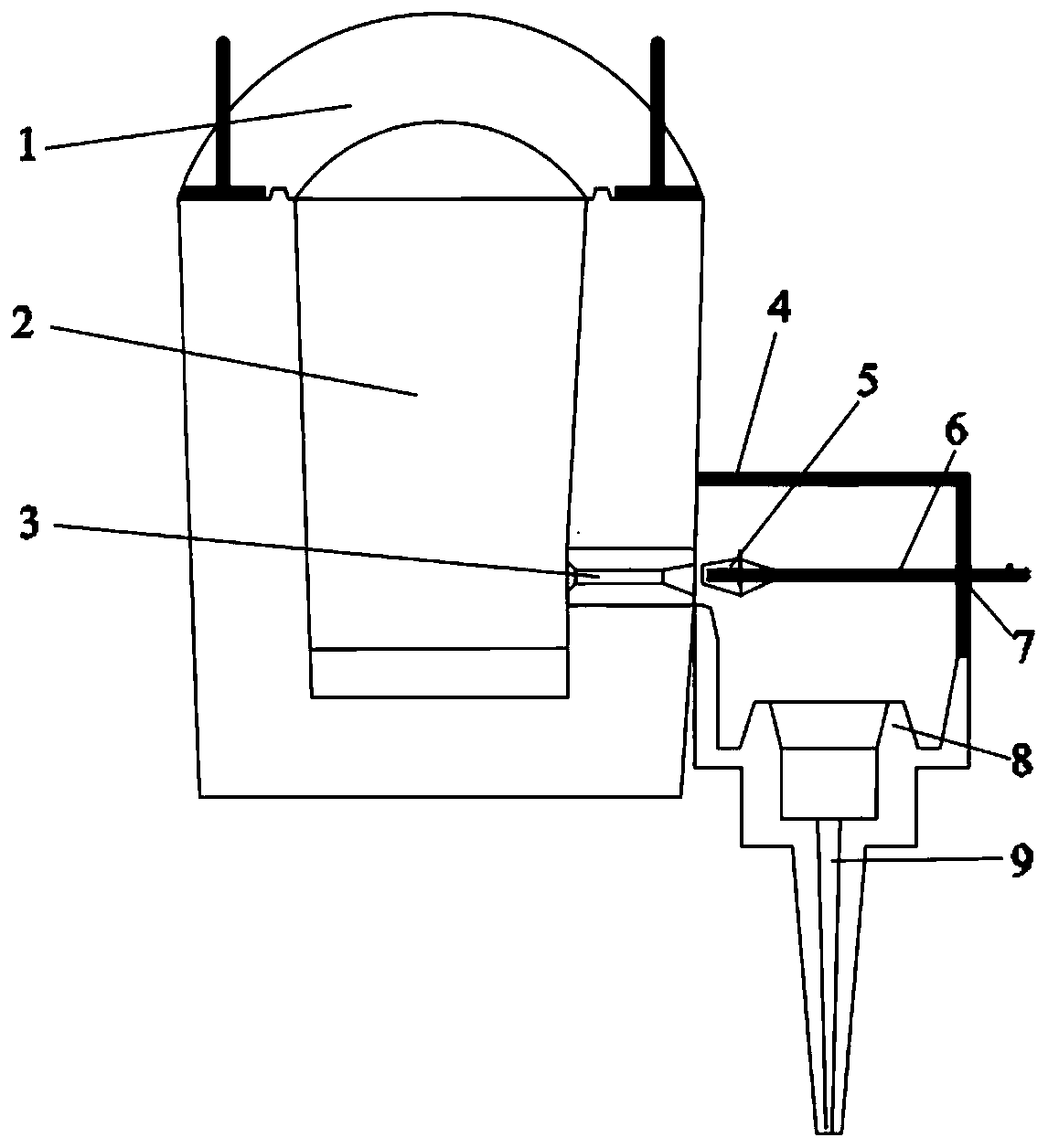
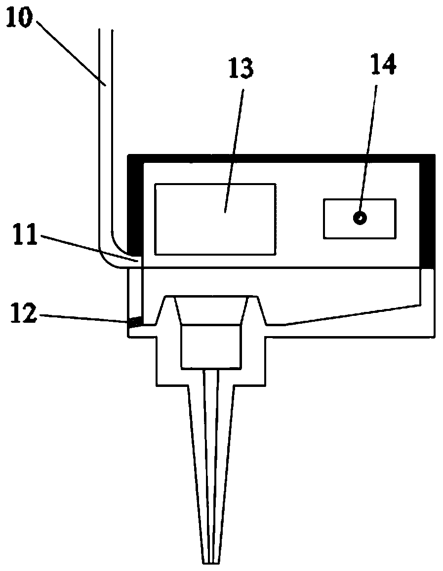
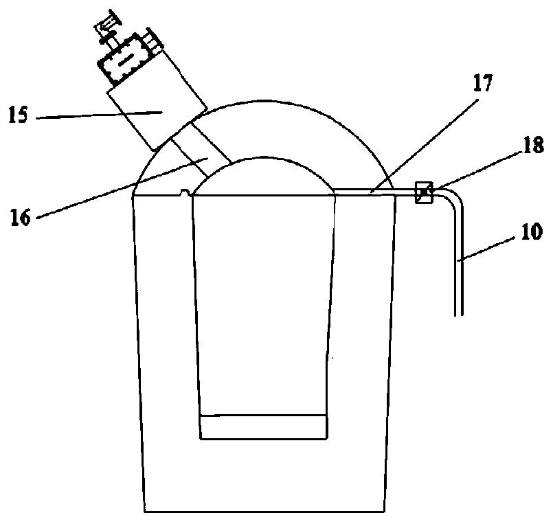
[0072] A liquid slag waste heat recovery system, including a slag buffer device, a flow control device, a centrifugal granulation device and a moving bed device; one end of the slag buffer device is connected to the slag ditch, and the other end of the slag buffer device is connected to the flow control device The inlet end of the flow control device is connected to the inlet end of the centrifugal granulation device, and the outlet end of the centrifugal granulation device is connected to the moving bed device; after the liquid slag is discharged from the slag ditch, it first enters the slag buffer device , and then pass through flow control device, centrifugal granulation device and moving bed device in sequence.

[0073] The slag buffering device includes a slag ladle body and a slag ladle cover; the slag ladle cover is sealed and arranged above the slag ladle body, and the s...

Embodiment approach

[0095] a) Open the flue gas outlet gap around the top of the granulation bin, the flue gas flows into the flue gas annular header through the flue gas outlet gap around the granulation bin, and finally set up a collection flue on the flue gas annular header to draw out the flue gas .

[0096] b) Open the flue gas outlet gap around the slag discharge pipe in the center of the granulation bin, the flue gas flows into the flue gas annular header through the flue gas outlet gap in the center of the granulation bin, and finally set up a collection flue on the flue gas annular header to lead out smoke.

[0097] In the connecting section between the moving bed waste heat recovery device and the granulation rotor, a slag cotton scraper is installed. The slag cotton scraper is arranged on both sides of the granulation rotor, arranged at 180°, designed according to the sawtooth structure, and adopts 310S stainless steel for high temperature resistance material. In the early stage of w...


PUM


Abstract

The invention provides an operation method of a liquid slag buffer and flow control device. The operation method includes the steps of liquid slag buffer operation, flow measurement and control operation, online overhaul operation and accident handling operation. When conducting liquid slag buffering, after preheating an inner cavity of a slag bag to the specified temperature, a valve on a high-temperature flue is opened, high-temperature flue gas of the inner cavity of the slag bag is introduced into a seal cover, and after preheating to the specified temperature, slag is started to be fed from a slag inlet in one end of the slag bag for buffering; when conducting liquid slag flow control, a slag discharge port is opened, then a sizing nozzle is opened, and meanwhile a plug rod is inserted to be matched with the sizing nozzle for flow control; and when overhauling a single module, the plug rod is matched with the sizing nozzle, the sizing nozzle is closed to stop slag discharge, and meanwhile the slag discharge port in the bottom of the side edge of a liquid slag flow measurement and control module is opened to discharge stored slag of the module, after the stored slag of the liquid slag flow measurement and control module is discharged, an overhaul inlet of the seal cover is opened, foam mud is pumped into the sizing nozzle for blocking, and then overhauling can be conducted.

Description

technical field [0001] The invention relates to the technical field of blast furnace slag waste heat recovery, in particular to an operation method of a liquid slag buffer and a flow measurement and control device. Background technique [0002] After nearly 30 years of development, my country's steel production has increased significantly. Vertically, my country's crude steel output increased from 66 million tons in 1990 to 810 million tons in 2016, with a compound growth rate of 10.1%. Horizontally, my country's crude steel output reached 810 million tons in 2016, accounting for 50.5% of global output. During the iron and steel smelting process, a large amount of high temperature slag will be produced. It is estimated that the slag temperature of blast furnace slag can be as high as 1400-1550°C, and the sensible heat value per ton of high-temperature blast furnace slag can be as high as 1260-1880MJ / ton, which is equivalent to 60kg standard coal / ton. According to statisti...

Claims


Application Information

Patent Timeline
Patent Type & Authority Applications(China)
IPC IPC(8): C21B3/10
CPCC21B3/10C21B2400/072
Inventor 王树众肖照宇赵军吴志强李美全马琛徐宁文
Owner XI AN JIAOTONG UNIV
Learn More