
Tunnel construction lining and ballast bed relative displacement monitoring device

A technology for tunnel construction and relative displacement, which is applied in the direction of measuring devices, optical devices, instruments, etc., and can solve problems such as low efficiency, potential safety hazards, and short service life

Active Publication Date: 2021-04-20
中煤浙江测绘地理信息有限公司
View PDF8 Cites 1 Cited by
  • Summary
  • Abstract
  • Description
  • Claims
  • Application Information

AI Technical Summary

Problems solved by technology

[0005] The technical problem to be solved by the present invention is to provide a relative displacement monitoring device for road construction lining and ballast bed, so as to solve the problem of short service life, low efficiency, easy damage to sensor devices, labor-intensive, potential safety hazards and use of existing fiber grating displacement sensors. It is difficult to control the installation angle during tunnel monitoring

Method used


Image

  • Tunnel construction lining and ballast bed relative displacement monitoring device
  • Tunnel construction lining and ballast bed relative displacement monitoring device
  • Tunnel construction lining and ballast bed relative displacement monitoring device

Examples


Embodiment 1

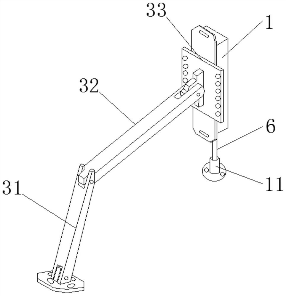
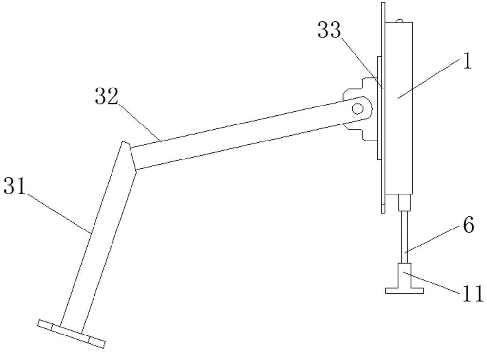
[0039] Refer to attached figure 1 with 2 As shown, the relative displacement monitoring device of the tunnel construction lining and the ballast bed involved in the present invention includes a fiber grating crack sensor, a tie rod fixing card and a bracket.

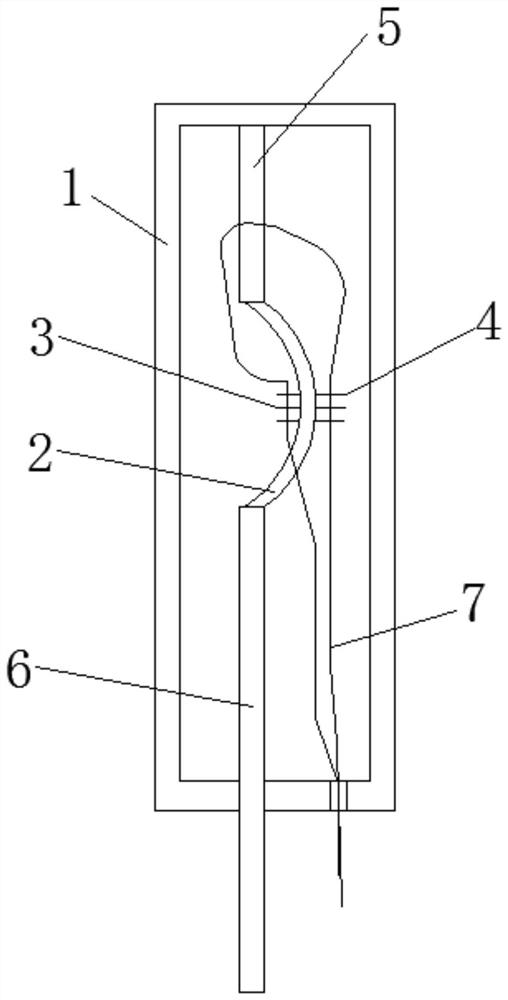
[0040] Refer to attached image 3 As shown, the fiber grating crack sensor involved in this embodiment includes a base 1 , a fixed boss 5 , a semicircular elastic piece 2 , a movable rod 6 , a first fiber grating 3 and a second fiber grating 4 . The top of the fixed boss 5 is fixed on the inside of the top plate of the base body 1, the top of the semicircular elastic sheet 2 is connected with the bottom of the fixed boss 5, and the top of the movable pull rod 6 is connected with the semicircular elastic sheet. The bottom end of 2 is connected, the movable pull rod 6 runs through the bottom plate of the base body 1, and the movable pull rod 6 is slidably connected with the base body 1; the first optical brazing grating ...

Embodiment 2

[0050] In order to make the monitoring of the device more accurate, this embodiment further improves the fiber grating crack sensor. On the basis of embodiment 1, two inclinometers 8 and a level adjustment device 9 are added, that is, two of them in the base body 1 Two adjacent sides are respectively provided with inclinometers 8 for adjusting the installation angle of the fiber grating crack sensor. The inclinometers 8 are embedded in the matrix 1, and one of the sides of the matrix 1 is provided with a level adjustment device 9; the level adjustment device 9 can be One of the inclinometers 8 is arranged on the same side of the base 1 , or it can be separated from the two inclinometers 8 and separately arranged on the other side of the base 1 .

[0051] Inclinometer 8 comprises a compass 81 and pointer 82, and compass 81 is provided with tilt scale 83, and the top of pointer 82 is hinged at the center of compass 81, and when inclinometer 8 is in vertical arrangement, the point...


PUM


Abstract

The invention relates to a tunnel construction lining and ballast bed relative displacement monitoring device. The device comprises a fiber bragg grating crack sensor, a pull rod fixing clamp and a support. The fiber bragg grating crack sensor comprises a base body, a fixed boss, a semi-circular elastic sheet and a movable pull rod, wherein the fixed boss, the semi-circular elastic sheet and the movable pull rod are arranged in the base body and sequentially connected from top to bottom, a first optical fiber bragg grating and a second optical fiber bragg grating are set on the left side face and right side face of the semi-circular elastic sheet, and the first optical fiber bragg grating and the second optical fiber bragg grating are connected with a conduction optical fiber extending out of the base body. The pull rod fixing clamp comprises a base, a rotating shaft and a connecting rod, the rotating shaft is rotatably installed in the base, and the connecting rod is used for being connected with the movable pull rod; the support comprises a supporting arm, a swing arm and a mounting plate and is used for adjusting the position and angle of the fiber grating crack sensor. The device is simple and compact in structure, resistant to electromagnetic interference, capable of achieving temperature self-compensation and long-term real-time online monitoring, long in service life and convenient to adjust in position and angle.

Description

technical field [0001] The invention belongs to the field of tunnel construction monitoring, in particular to a monitoring device for the relative displacement of a tunnel construction lining and a ballast bed. Background technique [0002] Displacement monitoring is one of the most basic measurement items in structural health monitoring, and it is also the basis for monitoring changes in various physical quantities (such as: stress and strain, settlement, inclination, acceleration, etc.). It plays an important role in the deformation, cracking and sliding monitoring of structures. At present, traditional electrical sensors are the most widely used in displacement monitoring. However, electrical sensors have disadvantages such as susceptibility to electromagnetic interference, poor stability, difficulty in long-term real-time monitoring, and vulnerability to complex and harsh field working environments. Displacement deformation measurement is difficult. The measurement accu...

Claims


Application Information

Patent Timeline
Patent Type & Authority Applications(China)
IPC IPC(8): G01B11/04
CPCY02E10/20
Inventor 杜海军丁智段月辉徐兵江涛何钰府伟娟王瞭王德传周玉清韩月
Owner 中煤浙江测绘地理信息有限公司
Learn More