DIC-based tooth root bending stress detection system and method in RV reducer gear engagement process

A technology of meshing process and bending stress, applied in the direction of applying stable bending force to test the strength of materials, instruments, measuring devices, etc., can solve the problems of reducing the structural strength of gear teeth, complex operation of gear bending fatigue test, and inaccurate measurement results

Active Publication Date: 2021-04-23
NINGBO UNIV
View PDF10 Cites 0 Cited by
  • Summary
  • Abstract
  • Description
  • Claims
  • Application Information

AI Technical Summary

Problems solved by technology

Strain gauge measurement There are two main methods for measuring gear displacement and strain: one is to stick strain gauges on the side of the gear, such as the invention patent with the authorized announcement number CN104266836B: test method and test device for tooth root bending fatigue durability, the patent Among them, the bending fatigue durability test is carried out by pasting strain gauges at the tooth root. Since the stress distribution at the tooth root is uneven, the measurement results are not accurate; the other is to drill holes and embed strain gauges on the tooth root surface Although this method can measure the displacement and strain at the tooth root surface, drilling holes at the tooth root surface will reduce the structural strength of the teeth, so the detection results are not accurate
The operation of the gear bending fatigue test is complicated, and the load operation test is affected by the transmission device. There is an error between the test result and the bending stress and strain at the root of the tooth. The pulsation fatigue testing machine mainly detects the ultimate bending fatigue data of the gear.

Method used


Image

  • DIC-based tooth root bending stress detection system and method in RV reducer gear engagement process
  • DIC-based tooth root bending stress detection system and method in RV reducer gear engagement process
  • DIC-based tooth root bending stress detection system and method in RV reducer gear engagement process

Examples


Embodiment Construction

[0044] The present invention will be further described in detail below in conjunction with the accompanying drawings and examples. The following examples are explanations of the present invention and the present invention is not limited to the following examples.

[0045] Example.

[0046] see Figure 1 to Figure 6 .

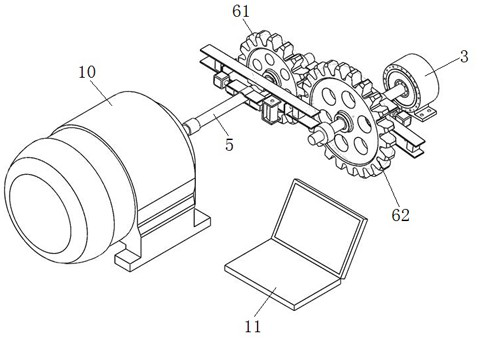
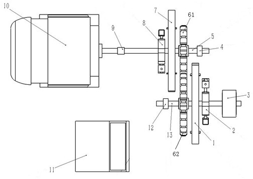
[0047] The embodiment discloses a DIC-based system for detecting the bending stress of the dedendum during the gear meshing process of the RV reducer, which is used for real-time detection of the bending stress at the tooth root during the meshing process of a pair of gears. In this embodiment, a pair of intermeshing gears are driven by a motor 10, and speckle is sprayed at the designated tooth root of each gear, and the speckle spraying area is determined according to the 30° tangent method, refer to Figure 5 shown.

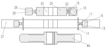
[0048] The detection system includes a magnetic torque motor power device 3 , two sets of DIC equipment, two photoelectric encoders and a hos...


PUM


Abstract

The invention relates to a DIC-based tooth root bending stress detection system and method in an RV reducer gear engagement process. The detection system comprises a magnetic torque motor power device, two sets of DIC equipment and a host. The two sets of DIC equipment are in one-to-one correspondence with a pair of gears; the DIC equipment is arranged on the side faces of the gears and comprises DIC digital camera assemblies and plane mirror assemblies, the DIC digital camera assemblies shoot speckle images at the tooth roots of the gears corresponding to the DIC digital camera assemblies through reflection of the plane mirror assemblies, the DIC digital camera assemblies are in communication connection with the host, and the speckle images shot by the DIC digital camera assemblies are transmitted to the host to be processed; the magnetic torque motor power device is connected with one of the gears and used for providing loads for the pair of gears. The system and the method adopts non-contact measurement, the data acquisition process is simple, and the system and the method can be used in places where detection is difficult or contact measurement equipment cannot be installed.

Description

technical field [0001] The invention relates to the technical field of gear measurement, in particular to a DIC-based detection system and method for tooth root bending stress during gear meshing of an RV reducer. Background technique [0002] When the load acts on the gear, due to the high rigidity of the gear material, the gear tooth can be regarded as a cantilever beam, causing the maximum stress at the root of the tooth, that is, the bending stress. The gear needs to check the fatigue bending strength of the tooth root, especially if the tooth surface hardness is high, the tooth core strength is low, or the gear material is brittle. The stress concentration of the gear teeth will break after repeated loading. At present, there are two methods of gear bending fatigue test commonly used: one is to install the test gear pair on the gear testing machine for load running test; the other is to use a special fixture on the pulsation fatigue testing machine to pulsate the gear ...

Claims


Application Information

Patent Timeline
IPC IPC(8): G01N3/20G01N3/06G01N3/02
Inventor 房玺正娄军强李国平崔玉国柳丽罗利敏
Owner NINGBO UNIV
Why Eureka
Try Eureka