
An insulation skin separator for equal slitting of waste cables

A technology for waste cables and insulating skins, which is applied in the field of insulating skin separators for volume cutting, can solve the problems of high labor intensity and low efficiency, and achieve the effect of easy cutting

Active Publication Date: 2022-04-26
胡迎勋
View PDF0 Cites 0 Cited by
  • Summary
  • Abstract
  • Description
  • Claims
  • Application Information

AI Technical Summary

Problems solved by technology

[0004] The object of the present invention is to provide an insulation skin separator for equal slitting of waste and old cables that can automatically cut recycled waste cables in equal amounts and separate the insulation skins of the cut cables, so as to solve the above-mentioned background The problem of manually separating the insulation skin in the technology is labor-intensive and low-efficiency

Method used


Image

  • An insulation skin separator for equal slitting of waste cables
  • An insulation skin separator for equal slitting of waste cables
  • An insulation skin separator for equal slitting of waste cables

Examples


Embodiment 1

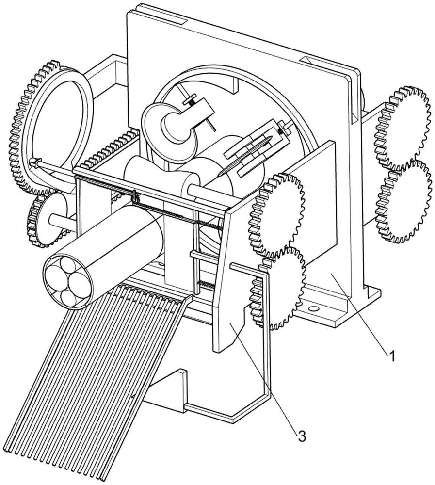
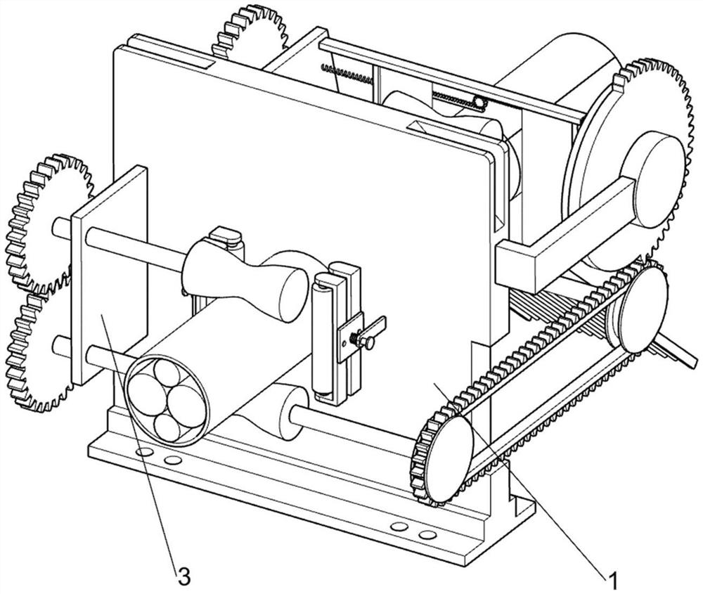
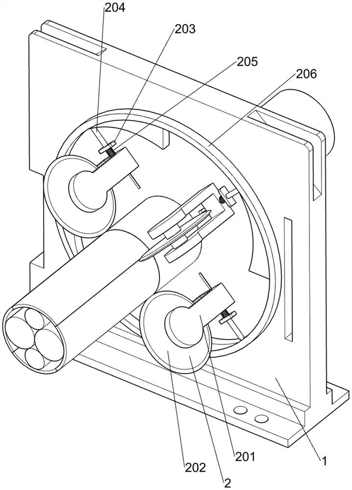
[0026] A kind of insulation skin separating machine for waste and old cable equivalent slitting, such as Figure 1-7 As shown, it includes a guide seat plate 1, a cutter position adjustment mechanism 2, a mounting plate 3, a cable support conveying mechanism 4, a cable cutting mechanism 5 and a cable sheath swing separation mechanism 6, and the cutter position adjustment mechanism 2 is located at On the guide seat plate 1, the cutter position adjustment mechanism 2 is used to make the cutting disc 202 just cut the insulation of the cable, and divide the insulation into four parts. The guide seat plate 1 is fixedly connected with the installation plate 3, and the cable The supporting conveying mechanism 4 is arranged on the mounting plate 3, the cable supporting conveying mechanism 4 is used to drive the cable to move in a direction close to the cutter plate 502, the cable cutting mechanism 5 is arranged on the mounting plate 3, and the cable cutting mechanism 5 is used for To ...

Embodiment 2

[0033] On the basis of Example 1, such as Figure 5 As shown, it also includes a support plate 7, a flattening roller frame 8 and a third compression spring 9, the support plate 7 is symmetrically fixed on the side of the guide seat plate 1 away from the cutter plate 502, and the support plate 7 is used to support the flattening The roller frame 8 and the third compression spring 9, and the flattening roller frame 8 are slidably arranged on the support plate 7 respectively, and the flattening roller frame 8 is used to squeeze the cable, so that the cable is squeezed more flat, which is convenient for subsequent alignment. When the cable is cut, a third compression spring 9 is connected between the support plate 7 and the flattening roller frame 8, and the third compression spring 9 is used to drive the flattening roller frame 8 to move and reset.

[0034] When the cable is in contact with the flattening roller frame 8, it will squeeze the two flattening roller frames 8 to move...


PUM


Abstract

The invention relates to an insulating skin separator, in particular to an insulating skin separator used for equal-quantity slitting of waste cables, comprising a guide seat plate, a cutter position adjustment mechanism, a mounting plate, a cable supporting and conveying mechanism and a cable Cutting mechanism, etc.; the cutter position adjustment mechanism is set on the guide seat plate, the guide seat plate is fixed with a mounting plate, the cable supporting and conveying mechanism is located on the mounting plate, and the cable cutting mechanism is located on the mounting plate. Through the cooperation of the cable cutting mechanism and the cable sheath swing separation mechanism, the recycled waste cables can be cut in equal amounts, and the insulating sheaths of the cut cables can be separated, so as to realize equal amount cutting and separation of the recycled waste cables. Function of cable insulation.

Description

technical field [0001] The invention relates to an insulation skin separator, in particular to an insulation skin separator for equal slitting of waste cables. Background technique [0002] Cable is a general term for optical cables, cables and other items. It is mainly composed of pvc plastic particle processing sheath insulation and copper wires of various specifications twisted into cables. There are many uses for cables, mainly used for control installation, connection equipment, power transmission, etc. Multiple functions are common and indispensable in daily life. [0003] my country's annual copper consumption is quite large, and a large part of the copper raw materials need to be imported from abroad. If the waste cables are reused, it can save a lot of foreign exchange every year, protect the environment, and save energy. The recycled Reuse of waste cables first requires separating the insulation of the outer layer of the cable. The existing insulation separation te...

Claims


Application Information

Patent Timeline
Patent Type & Authority Patents(China)
IPC IPC(8): H01B15/00
CPCH01B15/005Y02W30/82
Inventor 付山河
Owner 胡迎勋
Learn More