Switch tube

A switch tube and conductor technology, applied in the field of switch tubes, can solve the problems of poor reliability, high cost, and large bellows volume, and achieve the effects of good reliability and high mechanical life.

Pending Publication Date: 2021-04-27
BEIJING JINGREN ELECTRICAL CO LTD +1
View PDF0 Cites 0 Cited by
  • Summary
  • Abstract
  • Description
  • Claims
  • Application Information

AI Technical Summary

Problems solved by technology

[0006] 2. The bellows are large in size and high in cost
[0007] 3. The process is complicated and the reliability is poor, which is related to the life of the product
[0008] 4. Under the opening and closing action of the contacts, the elastic deformation of the bellows is prone to fatigue, resulting in air leakage and causing switch failure.

Method used


Image

  • Switch tube
  • Switch tube
  • Switch tube

Examples


no. 1 example

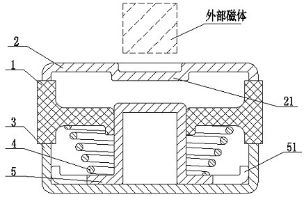
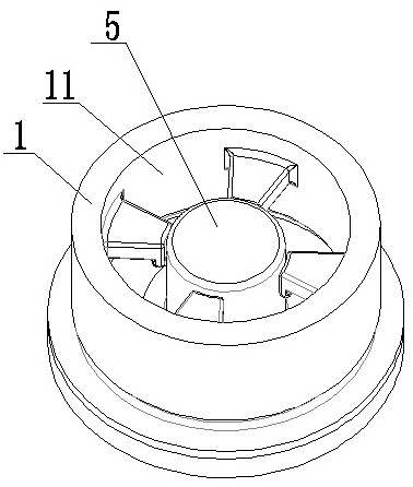
[0039] This embodiment discloses a switch tube, the switch tube includes an insulator 1, a first conductor 2 and a second conductor 3, and the first conductor 2 and the second conductor 3 are respectively arranged on the insulator 1 The two ends are welded and fixed to the insulator 1 respectively. The first conductor 2 and the second conductor 3 are respectively provided with cavities with opposite openings, the longitudinal section of the insulator 1 is H-shaped or I-shaped as a whole, and the insulator 1 is provided with a penetrating center hole, and the insulator 1, the first conductor 2 and the second conductor 3 are fixed to form a closed cavity. Preferably, the closed cavity is a vacuum structure, and the vacuum environment is favorable for breaking and arcing of the switch. off. Preferably, an arc-stopping gas such as nitrogen can be injected after vacuuming, and the nitrogen environment is favorable for breaking the switch and extinguishing the arc.

[0040] The in...

no. 2 example

[0045] Please refer to Figure 5 As shown, another form of switching tube is disclosed. The difference from the first embodiment is that the metal piece 5 includes a low-conductivity metal material and a high-conductivity material. The interior of the metal material with high conductivity, the metal material with low conductivity is set outside the metal material with high conductivity, or the metal material with low conductivity can also be set above or below the metal material with high conductivity, and the metal material with low conductivity is set below Taking the inside of the metal material with high conductivity as an example, the detailed description is as follows. The high conductivity material is copper or copper alloy, and the low conductivity metal material is permanent magnet or high magnetic permeability metal.

[0046] Please refer to Figure 5 As shown, the opening of the lower end of the metal part 5 is provided with a cover plate 53, and the cover plate 53...

no. 3 example

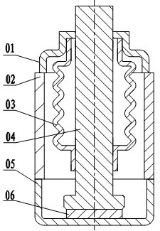
[0053] Please refer to Figure 7 As shown, this embodiment discloses another form of switch tube, which is the same as the second embodiment, the metal member 5 includes a low-conductivity metal material and a high-conductivity material, the difference lies in the structural form of the elastic member 4 Unlike the arrangement of the metal piece 5 in the second embodiment, the elastic piece 4 is in the form of a bellows, and the flexible conductor 6 and the metal piece between the metal piece 5 and the second conductor 3 are eliminated. 5 a boss 51 in contact with the second conductive member 3 .

[0054] Specifically, please refer to Figure 7 As shown, a permanent magnet 54 is provided in the inner cavity of the metal part 5, and the elastic part 4 adopts the structure of a bellows, one end of which is welded to the outer circle of the metal part 5, and the other end is connected to the second conductive part. body 3 is welded and fixed, and when the metal part 5 is in cont...


PUM


Abstract

The invention discloses a switch tube, which comprises an insulator (1), a first conductor (2) and a second conductor (3), wherein the first conductor (2) and the second conductor (3) are respectively arranged at two ends of the insulator (1) and jointly form a closed cavity, and an elastic piece (4) and a metal piece (5) capable of being driven by an external magnetic field are arranged in the closed cavity. Movement of the switch tube execution system is driven by an external permanent magnet or an electromagnet, connection and disconnection of an internal moving contact are achieved, the outside does not make direct contact with an internal moving part, parts do not deform elastically, elastic fatigue of the parts does not occur, the mechanical life is long, and reliability is good.

Description

technical field [0001] The invention relates to the technical field of low-voltage electrical appliances, in particular to a switch tube. Background technique [0002] In the high and low voltage distribution network, where high breaking and explosion-proof are especially required, the vacuum switch has an absolute advantage. The core component of the vacuum switch is a switch tube, or a vacuum interrupter. At present, it generally includes an upper cover, a ceramic seat, and a bottom. Cover, moving contact, bellows. The key technology of the existing product is the sealing of the switch tube, which is realized by welding the bellows between the bottom cover and the moving contact. The bellows is required to ensure good sealing while being attached to the elastic deformation of the bottom cover and the moving contact. However, the bellows is made of metal, with small deformation, high stress, and difficult welding, which has caused problems such as high cost of the switch t...

Claims


Application Information

Patent Timeline
Patent Type & Authority Applications(China)
IPC IPC(8): H01H33/66H01H33/662H01H33/664H01H33/666
CPCH01H33/6606H01H33/66207H01H33/664H01H33/666H01H2033/66215H01H2033/66223H01H33/66H01H33/662
Inventor 南寅吴国亮张晓璟邓艺军李军挺
Owner BEIJING JINGREN ELECTRICAL CO LTD
Why Eureka
Try Eureka