Ceramic particle wet spraying equipment for surface treatment of electronic materials and spraying method thereof
A technology of ceramic particles and electronic materials, applied in the direction of spraying devices, liquid spraying devices, etc., can solve problems such as excessive spraying and uneven spraying on the surface of electronic materials
- Summary
- Abstract
- Description
- Claims
- Application Information
AI Technical Summary
Problems solved by technology
Method used
Image
Examples
Embodiment 1
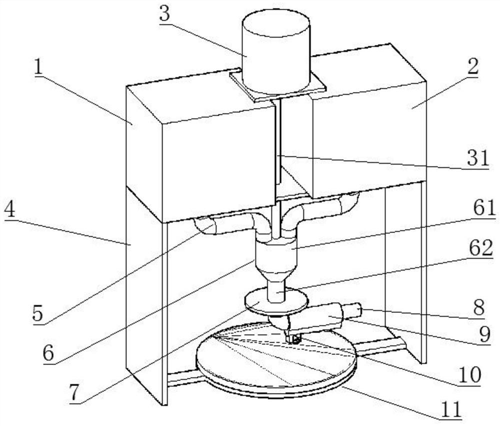
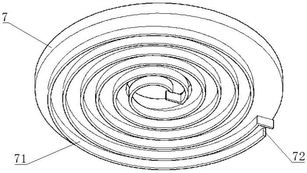
[0032] like Figure 1-2 As shown, the ceramic particle wet spraying equipment for surface treatment of electronic materials includes a material box, and the material box includes a particle cavity 1 and a water cavity 2. The particle cavity 1 and the water cavity 2 are respectively connected with the mixing pipe 6 through the connecting pipe 5, and the mixing A screw mixing shaft is rotatably connected in the material pipe 6, and the bottom end of the screw mixing shaft is fixedly connected with the spray pipe 8. The spray pipe 8 is connected with the mixing pipe 6 in a sealed rotation. The port 81 is communicated with the nozzle 10 which is axially slidably connected on the nozzle 8. The top of the nozzle 10 is connected with a limit rod 12, and the limit rod 12 is slidably connected with the limit plate 7 fixedly connected to the outside of the mixing pipe 6. The bottom of the limit plate 7 A spiral limiting groove 71 is provided on the side, and a stage 11 is provided below...
Embodiment 2
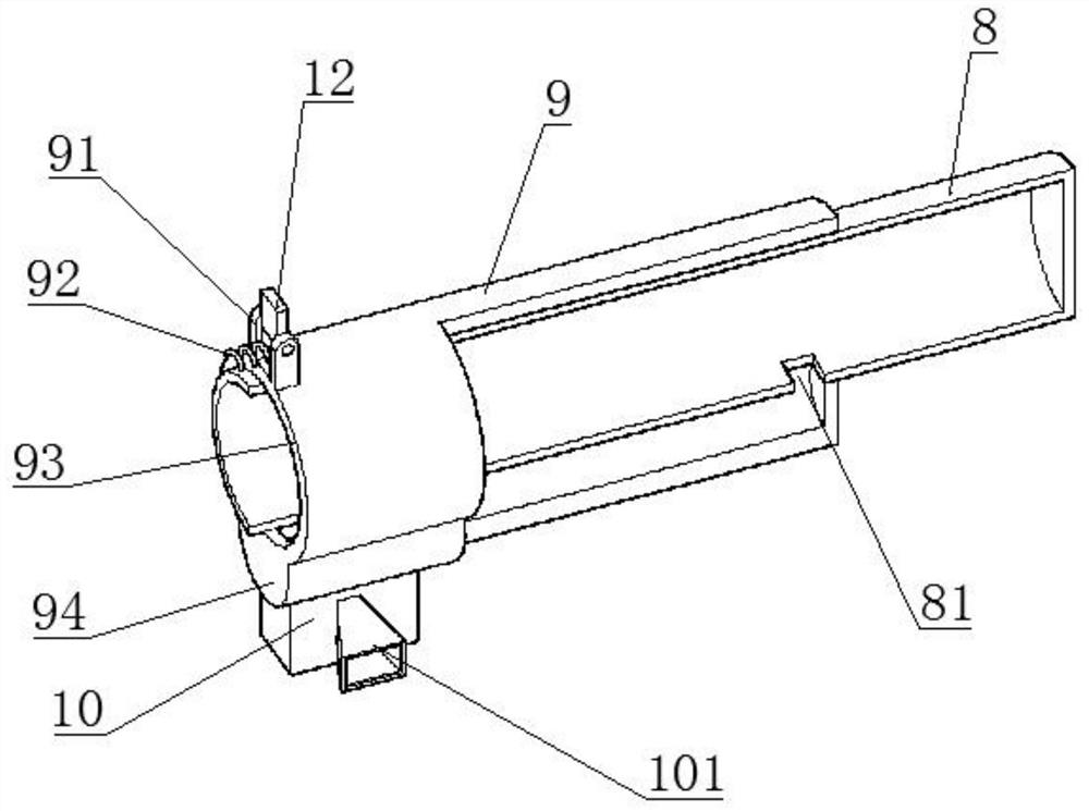
[0035] like Figure 1-4As shown, the ceramic particle wet spraying equipment for surface treatment of electronic materials includes a material box, and the material box includes a particle cavity 1 and a water cavity 2. The particle cavity 1 and the water cavity 2 are respectively connected with the mixing pipe 6 through the connecting pipe 5, and the mixing A screw mixing shaft is rotatably connected in the material pipe 6, and the bottom end of the screw mixing shaft is fixedly connected with the spray pipe 8. The spray pipe 8 is connected with the mixing pipe 6 in a sealed rotation. The port 81 is communicated with the nozzle 10 which is axially slidably connected on the nozzle 8. The top of the nozzle 10 is connected with a limit rod 12, and the limit rod 12 is slidably connected with the limit plate 7 fixedly connected to the outside of the mixing pipe 6. The bottom of the limit plate 7 A spiral limiting groove 71 is provided on the side, a stage 11 is provided below the ...
Embodiment 3
[0038] like Figure 1-6 As shown, the ceramic particle wet spraying equipment for surface treatment of electronic materials includes a material box, and the material box includes a particle cavity 1 and a water cavity 2. The particle cavity 1 and the water cavity 2 are respectively connected with the mixing pipe 6 through the connecting pipe 5, and the mixing A screw mixing shaft is rotatably connected in the material pipe 6, and the bottom end of the screw mixing shaft is fixedly connected with the spray pipe 8. The spray pipe 8 is connected with the mixing pipe 6 in a sealed rotation. The port 81 is communicated with the nozzle 10 which is axially slidably connected on the nozzle 8. The top of the nozzle 10 is connected with a limit rod 12, and the limit rod 12 is slidably connected with the limit plate 7 fixedly connected to the outside of the mixing pipe 6. The bottom of the limit plate 7 A spiral limiting groove 71 is arranged on the side, a stage 11 is arranged below the...
PUM
 Abstract
Description
Claims
Application Information
 - R&D
- Intellectual Property
- Life Sciences
- Materials
- Tech Scout
- Unparalleled Data Quality
- Higher Quality Content
- 60% Fewer Hallucinations
Browse by: Latest US Patents, China's latest patents, Technical Efficacy Thesaurus, Application Domain, Technology Topic, Popular Technical Reports.
© 2025 PatSnap. All rights reserved.Legal|Privacy policy|Modern Slavery Act Transparency Statement|Sitemap|About US| Contact US: help@patsnap.com


