Basic shaft type SLM metal printer

A printer and base shaft technology, which is applied in the field of base shaft SLM metal printers, can solve the problems of single powder feeding, uncontrolled temperature stress of the workpiece, and affecting the use effect, etc.

Active Publication Date: 2021-04-30
嘉兴意动能源有限公司
View PDF8 Cites 3 Cited by
  • Summary
  • Abstract
  • Description
  • Claims
  • Application Information

AI Technical Summary

Problems solved by technology

[0006] 1. It is necessary to set up complex mechanism components such as powder spreading device and powder scraping device;
[0007] 2. It cannot meet the requirements of processing symmetry of some rotating parts;
[0008] 3. The quality of printed and processed products cannot be guaranteed, and the temperature and stress of the workpiece during printing are not controlled, which may easily cause defects such as stress concentration
[0009] 4. The base shaft driving device used in some existing base shaft type SLM metal printers has a simple structure, which cannot realize the rotation and up and down movement

Method used


Image

  • Basic shaft type SLM metal printer
  • Basic shaft type SLM metal printer
  • Basic shaft type SLM metal printer

Examples


Embodiment 1

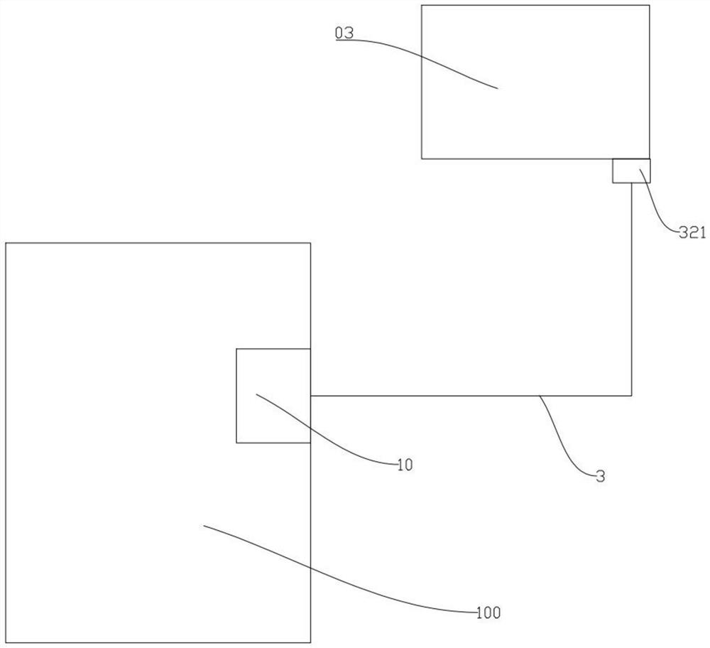
[0067] Such as Figures 1 to 11 As shown, a base shaft type SLM metal printer, including a printer body and a metering powder feeding device;

[0068] The powder inlet of the metering powder feeding device is connected with the powder replenishing mechanism of the printer body through the powder feeding pipe;

[0069] The printer body includes a frame;

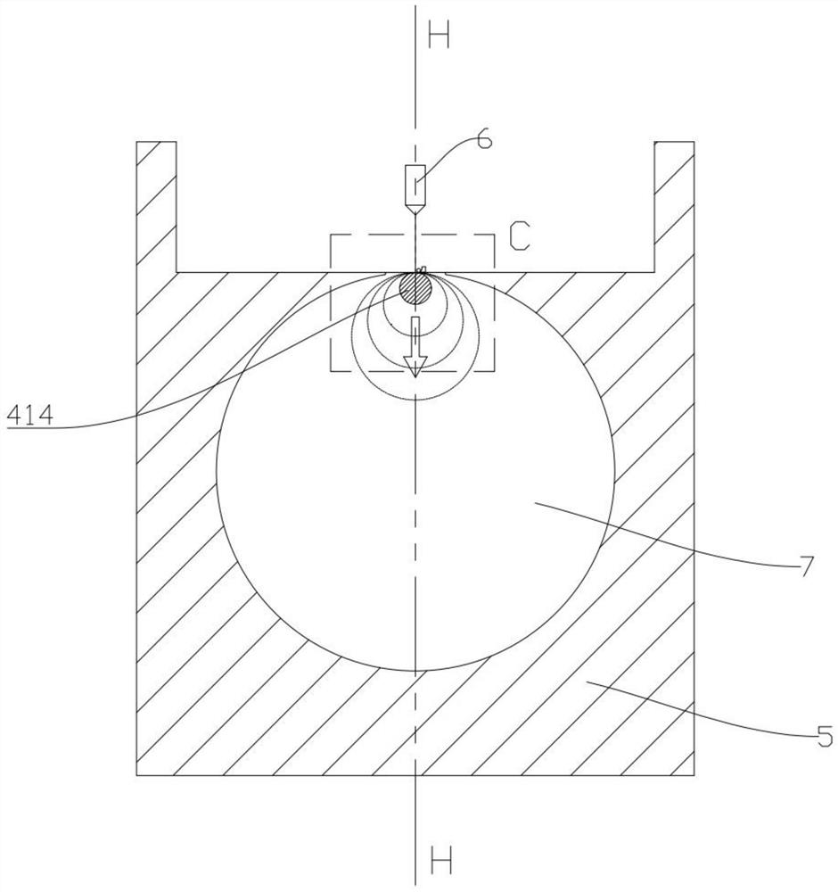
[0070] The middle part of the frame is provided with a powder cylinder;

[0071] The powder cylinder is in the shape of a cylinder, and its extension direction is parallel to the horizontal plane;

[0072] A base shaft driving device is arranged in the powder cylinder;

[0073] The mounting plates on both sides of the base shaft driving device are respectively detachably and fixedly connected to the inner lower surface of the powder cylinder;

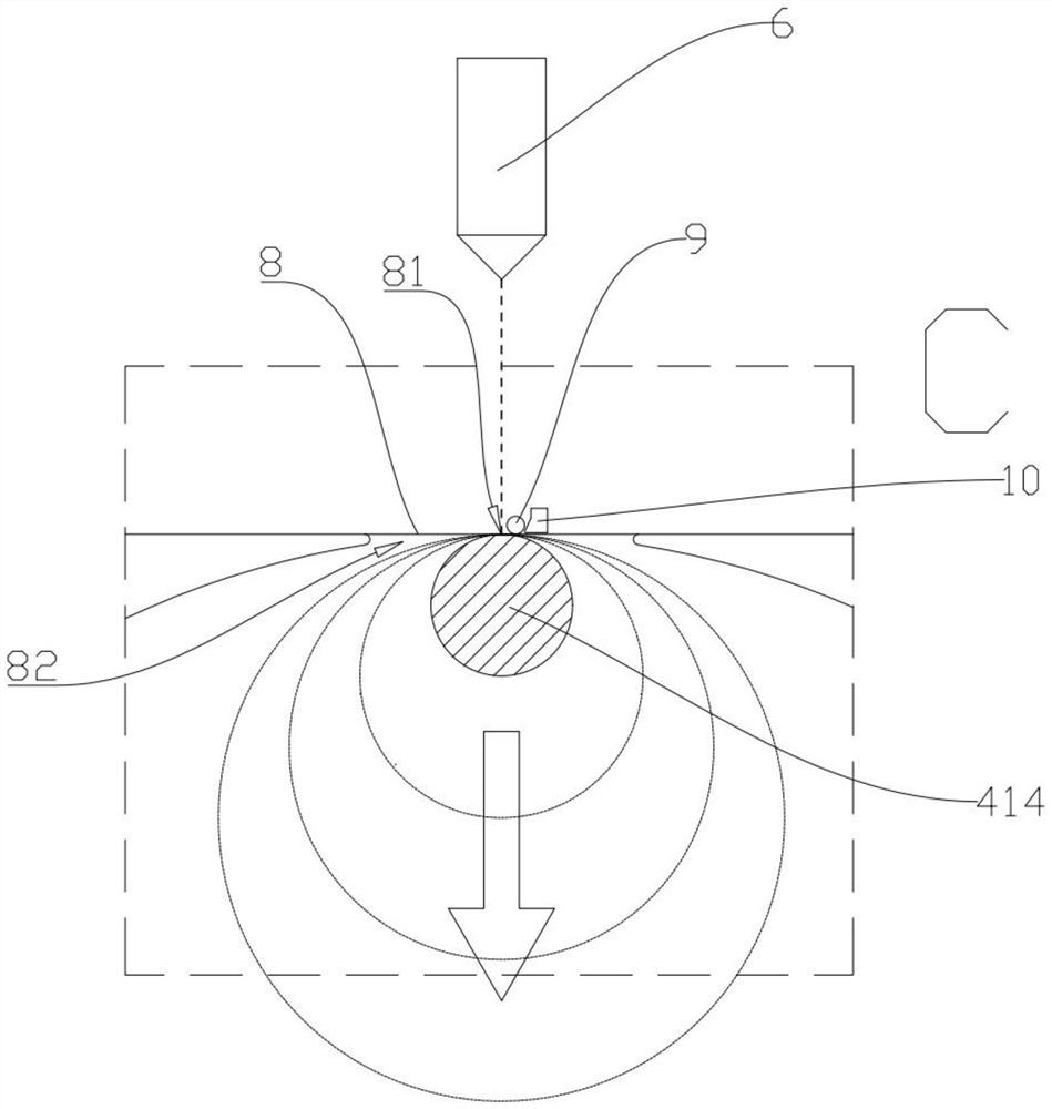
[0074] The base shaft driving device is used to drive the base shaft to rotate and / or move up and down;

[0075] The extension direction of the base shaft is the same as the extens...

Embodiment 2

[0081] Such as Figures 1 to 11 As shown, a base shaft type SLM metal printer, including a printer body and a metering powder feeding device;

[0082] The powder inlet of the metering powder feeding device is connected with the powder replenishing mechanism of the printer body through the powder feeding pipe;

[0083] The printer body includes a frame;

[0084] The middle part of the frame is provided with a powder cylinder;

[0085] The powder cylinder is cylindrical, preferably cylindrical, and its extension direction (axis direction) is parallel to the horizontal plane;

[0086] A base shaft driving device is arranged in the powder cylinder;

[0087] The mounting plates on both sides of the base shaft driving device are respectively detachably and fixedly connected to the inner lower surface of the powder cylinder;

[0088] The base shaft driving device is used to drive the base shaft to rotate and / or move up and down;

[0089] The extension direction of the base shaft...


PUM


Abstract

The invention discloses a basic shaft type SLM metal printer which comprises a printer body and a metering powder feeding device. The printer body comprises a rack; a powder cylinder is arranged in the middle of the rack; the powder cylinder is cylindrical, and the extending direction of the powder cylinder is parallel to the horizontal plane; a basic shaft driving device is arranged in the powder cylinder; the basic shaft driving device is used for driving the basic shaft to rotate and/or move up and down; the powder cylinder is provided with a long-strip-shaped opening, crack pieces are connected to the two sides of the long-strip-shaped opening, and a gap is formed between the two crack pieces; a powder scraping roller is arranged on one side below the gap; and a powder supplementing mechanism is further arranged in the powder cylinder. The basic shaft type SLM metal printer is simple in structure and convenient to use, complex components such as a powder laying device and a powder scraping device are omitted, the requirements for machining symmetry and the like of some rotating components are well met, the quality of printed and machined products is guaranteed, the temperature stress of workpieces in the printing process is controlled, automatic feeding is achieved, and the printing efficiency is improved.

Description

technical field [0001] The invention relates to the technical field of SLM printing equipment, in particular to a base shaft type SLM metal printer. Background technique [0002] SLM is Selective LaserMelting, selective laser melting, is a more industrialized method of 3D printing, moving the roller to push the metal particles through the printing area, and then the powerful laser will track the current layer of the printed object, and selectively melt it according to the designed model. Parts of the particles are fused together, once the current layer is complete, the roller moves back and forth again, bringing a new layer of metal particles, when using SLM the metal particles are actually completely melted and they fuse together more strongly, forming the Extremely strong objects, these parts can also be printed as a whole without the need to assemble different parts, which further reduces the possibility of failure or error during assembly, based on the benefits of this d...

Claims


Application Information

Patent Timeline
IPC IPC(8): B22F12/00B22F10/28B22F12/57B22F12/63B22F12/30B33Y30/00B33Y40/00
CPCB22F3/003B33Y30/00B33Y40/00Y02P10/25
Inventor 韩品连
Owner 嘉兴意动能源有限公司
Why Eureka
Try Eureka