Supercharge Your Innovation With Domain-Expert AI Agents!

Powder flow detection device and method

A flow detection device and flow detection technology, applied in the direction of additive manufacturing, additive processing, etc., can solve problems such as structure and performance to be improved, and achieve the effect of reasonable structure, improved stability and quality, and significant technical effect.

Active Publication Date: 2021-04-30
SHANGHAI AEROSPACE EQUIP MFG GENERAL FACTORY
View PDF7 Cites 2 Cited by
  • Summary
  • Abstract
  • Description
  • Claims
  • Application Information

AI Technical Summary

Problems solved by technology

The structure and performance of this patent still have room for improvement

Method used


Image

  • Powder flow detection device and method
  • Powder flow detection device and method
  • Powder flow detection device and method

Examples


Embodiment Construction

[0052] The present invention will be described in detail below in conjunction with specific embodiments. The following examples will help those skilled in the art to further understand the present invention, but do not limit the present invention in any form. It should be noted that those skilled in the art can make several changes and improvements without departing from the concept of the present invention. These all belong to the protection scope of the present invention.

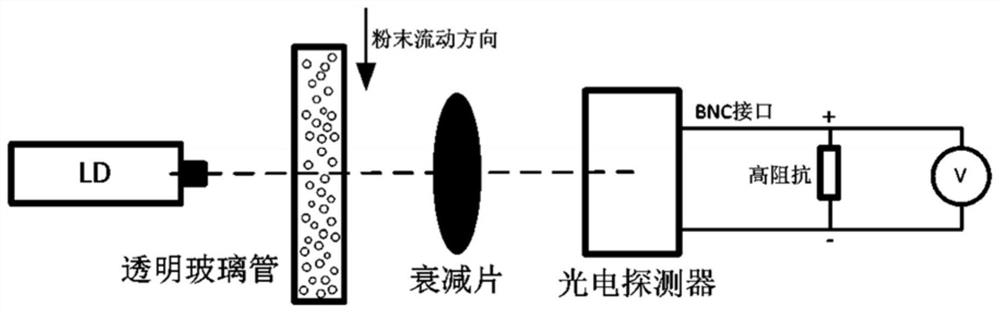
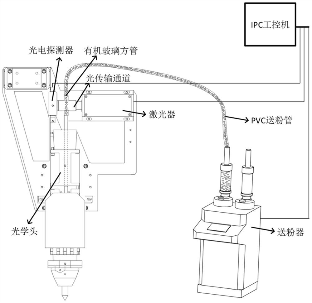
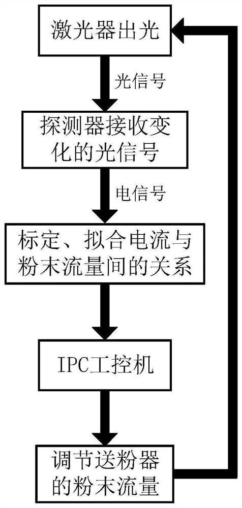
[0053] The invention provides a powder flow detection device and method, which are suitable for the field of optical detection of additive manufacturing equipment, and provide a powder flow detection solution and a device for the change of the powder feeding amount during the forming process of the equipment that cannot be directly observed. The method and device mainly include a laser, a photodetector, a control system and a transmission channel. The laser is used as the emission source, and the photod...


PUM

PropertyMeasurementUnit
transmittivityaaaaaaaaaa

Abstract

The invention provides a powder flow detection device and method. The detection device comprises a powder feeding device (1), a powder feeding pipe (2), a laser device (3), a light transmission channel (4), a square pipe (5), an optical detector (6) and an optical head (7). The powder feeding device (1) is connected with the powder feeding pipe (2). The powder feeding pipe (2) is connected with the square pipe (5). The square pipe (5) is connected with the light transmission channel (4). The light transmission channel (4) is connected with the laser device (3). The light transmission channel (4) is connected with the optical detector (6). The optical head (7) is connected with the light transmission channel (4). The device can detect powder flow in the machining process of additional material manufacturing equipment, and by means of quantization of powder flow parameters, machining stability and quality of the equipment are improved.

Description

technical field [0001] The invention relates to the technical field of laser powder additive manufacturing, in particular to a powder flow detection device and method. Background technique [0002] The powder feeding amount is an important process parameter in the powder additive manufacturing equipment. During the long-term operation of the equipment, there are often situations such as insufficient powder remaining or powder feeder failure, so that the powder feeding amount under the working state does not meet the process requirements, thus Causes the part to fail to print. At the same time, laser powder additive manufacturing equipment needs to calibrate the powder output of the powder feeder from time to time, which reduces the use efficiency of the equipment. Therefore, the closed-loop control of the powder output during the printing process of the equipment is very critical, which can effectively improve the success rate of equipment printing and provide assistance fo...

Claims


Application Information

Patent Timeline
Patent Type & Authority Applications(China)
IPC IPC(8): B22F12/57B22F10/28B33Y30/00B33Y50/00
CPCB33Y30/00B33Y50/00Y02P10/25
Inventor 王旭琴赵凯杜洋刘正武孙靖邓文敬王毅
Owner SHANGHAI AEROSPACE EQUIP MFG GENERAL FACTORY
Features
  • R&D
  • Intellectual Property
  • Life Sciences
  • Materials
  • Tech Scout
  • Unparalleled Data Quality
  • Higher Quality Content
  • 60% Fewer Hallucinations
Learn More