
A hydraulic actuator and UAV landing gear

A technology for actuators and UAVs, applied in the chassis and other directions, can solve problems affecting the overall performance of UAVs, increase self-weight and occupied space, and complicate manufacturing of electronic systems, so as to achieve small space occupation, prevent adverse effects, and light self-weight Effect

Active Publication Date: 2021-07-09
常州市科惠电力设备有限公司
View PDF4 Cites 0 Cited by
  • Summary
  • Abstract
  • Description
  • Claims
  • Application Information

AI Technical Summary

Problems solved by technology

However, the manufacturing of electronic systems is complicated and the reliability is not very sufficient. Even if some other design ideas are adopted, the overall structure is also complicated and takes up a lot of space.
[0004] For large aircraft, the above-mentioned problems of complexity, increased self-weight and large space occupation can be overcome or accepted, but for UAVs, especially small and medium-sized UAVs such as UAVs used for agricultural and forestry operations Or consumer drones, the complexity of the system, the increase in weight and the problem of taking up a large space will seriously affect the overall performance of the drone
Therefore, in view of the complexity of the hydraulic control structure of the traditional aircraft, the increase in dead weight and the large space occupied, the existing unmanned aerial vehicle landing gear folding mechanism does not use a hydraulic mechanism. For example, the patent document CN107352018A discloses a foldable unmanned Aircraft landing gear, patent document CN108177762A discloses a design of a rapid retractable folding mechanism for a multi-rotor UAV landing gear, all of which only use the way of component connection to realize simple retractable folding
However, these components have many exposed parts, and it is not conducive to modular production to adapt to different models or different types of drones

Method used


Image

  • A hydraulic actuator and UAV landing gear
  • A hydraulic actuator and UAV landing gear
  • A hydraulic actuator and UAV landing gear

Examples


Embodiment Construction

[0028] The present invention will be further described in detail below with reference to the embodiments given in the accompanying drawings. The described embodiments include various specific details to aid in understanding, but they are to be regarded only as exemplary, some, not all, embodiments of the invention. Meanwhile, detailed descriptions of functions and constructions well-known in the art will be omitted for clarity and conciseness of the description.

[0029] Unless otherwise defined, the technical terms or scientific terms used herein shall have the usual meanings understood by those skilled in the art to which the present invention belongs. The "upper", "lower" or "upper" and "lower" mentioned in this application are the upper and lower relationships roughly shown in the drawings of this application. When the placement state changes, for example, when it is turned over, the corresponding positional relationship should also be converted accordingly to understand ...


PUM


Abstract

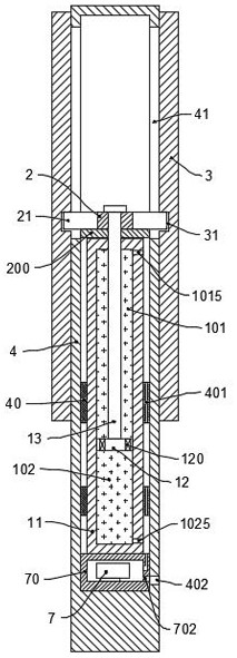
A hydraulic actuator, including a cylinder, a piston and a piston rod, the piston is installed in the cylinder and the inside of the cylinder is divided into a first oil chamber and a second oil chamber; the piston rod is connected with a first actuator, and the first actuator The element is provided with a first actuator rod end; it also includes a second actuator and a guiding and fixing cylinder. The end of the actuator rod is installed in the second actuator ring groove through the guide longitudinal groove; there are more than two straight-through check valves on the piston, and the straight-through check valve is set so that when the piston moves to the direction of the first oil chamber, The straight-through check valve is opened by the oil pressure in the first oil chamber and communicates with the first oil chamber and the second oil chamber. The complexity of the hydraulic system is reduced, the self-weight is light, the space occupied is small, and it can also be used as a functional part of the landing gear itself, so it can be applied to small and medium-sized UAVs such as UAVs for agricultural and forestry operations or consumer UAVs.

Description

technical field [0001] The invention relates to a hydraulic actuator used for the landing gear of an unmanned aerial vehicle. Background technique [0002] Typically the landing gear of an aircraft needs to be retracted for flight during use and released for landing. Generally, an aircraft uses multiple hydraulic subsystems as a driving source. For example, the patent document CN105782148A discloses a hydraulic device for retracting and retracting the landing gear of a helicopter. A variable frequency motor is used to control a quantitative hydraulic pump. A hydraulic device for retracting and retracting the landing gear. The landing gear retractable system with this structure has a simple structure, unlimited installation position, low requirements on oil precision, and abandons the valve-controlled throttling and speed-regulating servo hydraulic system, avoiding throttling loss and overflow loss. The temperature of the system is raised and the efficiency is low. At the s...

Claims


Application Information

Patent Timeline
Patent Type & Authority Patents(China)
IPC IPC(8): B64C25/22
CPCB64C25/22
Inventor 程进戴曙光陶必能杨振宇
Owner 常州市科惠电力设备有限公司
Learn More