Furniture gap blocking rubber strip winding process
A technology of rubber strips and gaps, applied in the field of furniture, can solve the problems of wasting working time, poor service life, easy to break, etc.
- Summary
- Abstract
- Description
- Claims
- Application Information
AI Technical Summary
Problems solved by technology
Method used
Image
Examples
Embodiment 1
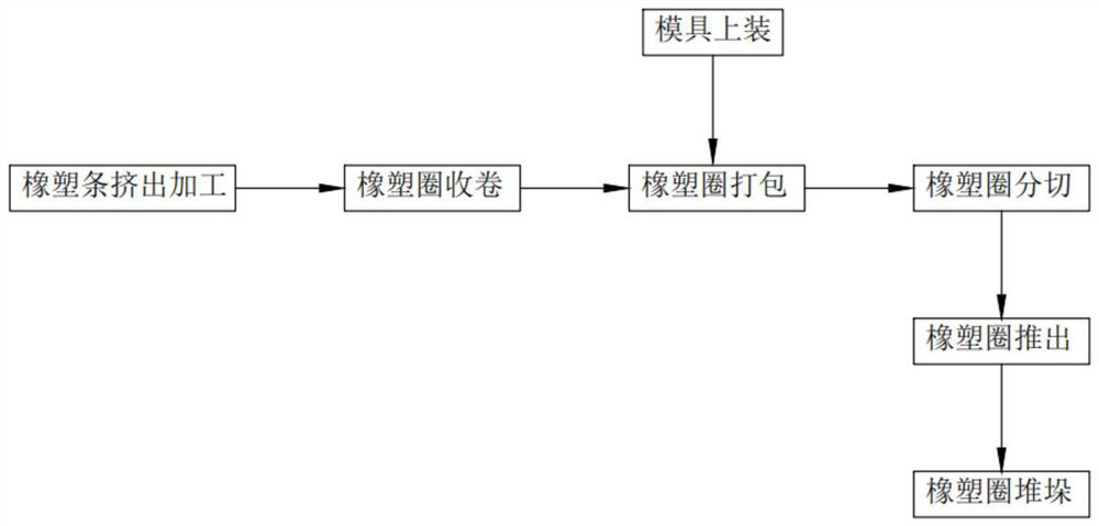
[0062] Such as figure 1 As shown, a furniture gap sealing rubber strip rolling process, including:
[0063] Step 1, extrusion processing of rubber and plastic strips, extruder 111 extrudes the rubber and plastic strips, cooling box 121 cools the extruded rubber and plastic strips, and then uses air drying box 123 to air dry them;
[0064] Step 2, the rubber and plastic ring is rolled up. After the rubber and plastic strips 10 are air-dried, when the first group of rubber and plastic strips are packaged, the tractor is manually sent into the two sets of clamping plates 2133, and the connecting frame a212 is manually passed through the handle 215. Send it into the horizontal part of the guide track a214, and the clamping unit 213 completes the clamping work on the rubber and plastic strip. At this time, the drive motor 2131 starts in reverse, and the drive motor 2131 drives the first follower 214 to drive the connecting frame a2121 to move horizontally, and then During the move...
Embodiment 2
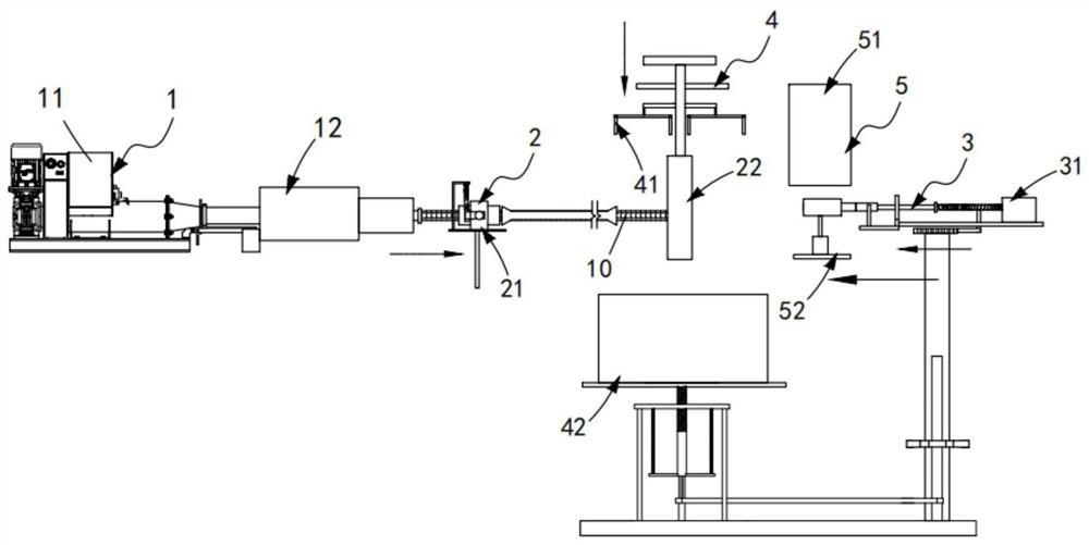
[0081] Such as figure 2 Shown, a kind of furniture gap sealing rubber strip continuous packaging equipment, including:
[0082] A transmission mechanism 1, the transmission mechanism 1 comprising an extruder 11 and a cooling assembly 12 arranged at the output end of the extruder 11;
[0083] A traction mechanism 2, the traction mechanism 2 includes a clamping component 21 disposed at the output end of the cooling component 12 and a support component 22 disposed on one side of the clamping component 21 and matched with the clamping component 21;
[0084] The winding mechanism 3, the winding mechanism 3 includes a hoop assembly 31 arranged on one side of the support assembly 22 and a cutting assembly synchronously driven with the hoop assembly 31 and used for cutting the rubber strip 10 32. A clamping mold 33 is placed on the hoop assembly 31;
[0085] A stacking mechanism 4, the stacking mechanism 4 includes a push-down assembly 41 arranged above the support assembly 22 and ...
Embodiment 3
[0134] Such as Figure 26 to Figure 31 As shown, the parts that are the same as or corresponding to those in the second embodiment are marked with the corresponding reference numerals in the second embodiment. For the sake of simplicity, only the differences from the second embodiment will be described below. The difference between this embodiment three and embodiment two is:
[0135] further, such as Figure 26 to Figure 28 As shown, the mold storage assembly 51 includes a storage box 511, two sets of guide posts 512 matched with the hoop 3321 and set in the storage box 511, two sets of guide posts 512 set in the two sets of guide posts 512 and a directional column 513 arranged in a right-angled triangle structure and a temporary storage unit 514 arranged at the bottom of the storage box 511. The temporary storage unit 514 is provided in several groups and includes a horizontally arranged telescopic unit m515 and an inverted The limit seat 516 of the corner structure, the h...
PUM
| Property | Measurement | Unit |
|---|---|---|
| width | aaaaa | aaaaa |
Abstract
Description
Claims
Application Information
 - R&D
- Intellectual Property
- Life Sciences
- Materials
- Tech Scout
- Unparalleled Data Quality
- Higher Quality Content
- 60% Fewer Hallucinations
Browse by: Latest US Patents, China's latest patents, Technical Efficacy Thesaurus, Application Domain, Technology Topic, Popular Technical Reports.
© 2025 PatSnap. All rights reserved.Legal|Privacy policy|Modern Slavery Act Transparency Statement|Sitemap|About US| Contact US: help@patsnap.com


