Wastewater collecting device of chemical industry equipment and working method of device

A waste water collection and equipment technology, applied in chemical instruments and methods, oxidized water/sewage treatment, multi-stage water treatment, etc., can solve problems such as inconvenient cleaning, single function, and affecting the speed of waste water collection

Inactive Publication Date: 2021-04-30
马鞍山天哲环保科技有限公司
View PDF0 Cites 1 Cited by
  • Summary
  • Abstract
  • Description
  • Claims
  • Application Information

AI Technical Summary

Problems solved by technology

[0002] The chemical industry is the general name of enterprises and units engaged in the production and development of the chemical industry; the chemical industry needs to use different chemical equipment during production; some chemical equipment will discharge waste water during the work process; the waste water contains more polluting substances , it is usually necessary to collect and treat waste water; the waste water collection device in the prior art has a simple structure and a single function, and only has the function of collecting waste water. Moreover, in the process of waste water treatment, floating objects in waste water are easy to block Pipelines affect the speed of waste water collection; moreover, waste water is stored inside the tank, and impurities will accumulate inside the tank, which is inconvenient to clean. Therefore, it is very important to design a waste water collection device for chemical industry equipment and its working method necessary

Method used


Image

  • Wastewater collecting device of chemical industry equipment and working method of device
  • Wastewater collecting device of chemical industry equipment and working method of device
  • Wastewater collecting device of chemical industry equipment and working method of device

Examples


Embodiment approach

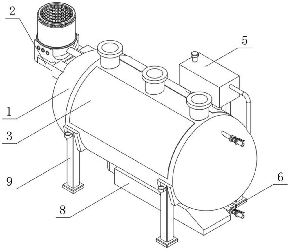
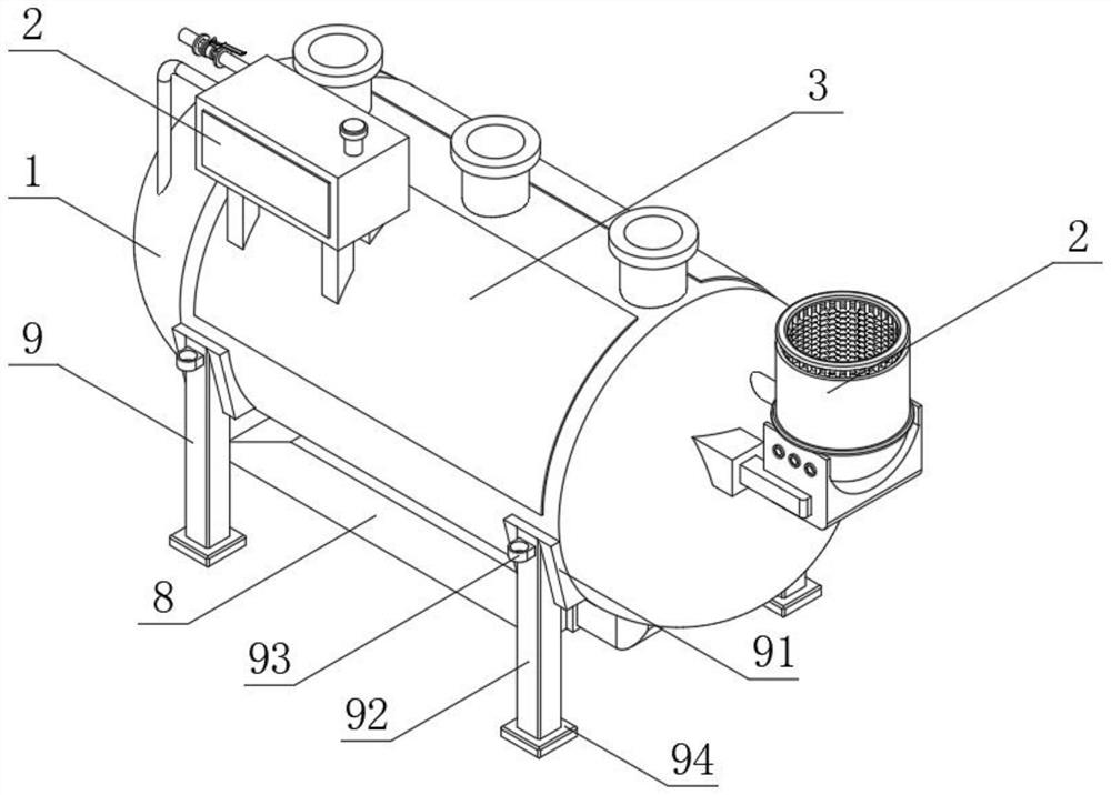
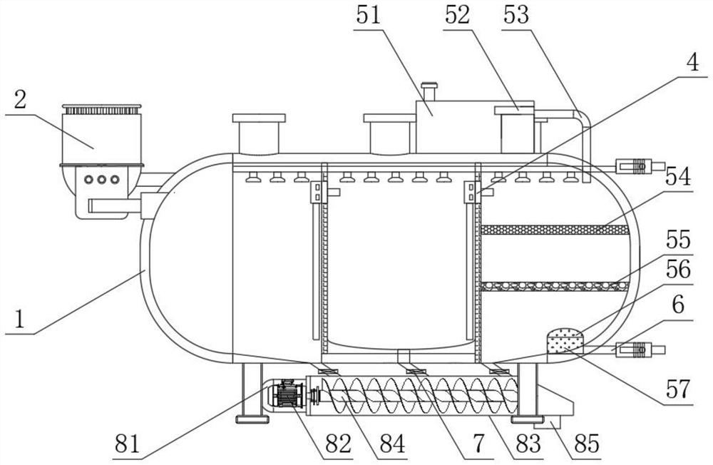
[0024] As an embodiment of the present invention, the primary filter assembly 2 includes a mounting arm frame 21, a connecting base plate 22, a bracket 23, a primary filter cartridge 24, a primary filter wire mesh 25 and a water inlet pipe 26, and the mounting arm frame 21 is fixedly installed by welding On both sides of the side end face of the water storage tank 1, the top end face of the mounting arm frame 21 is fixedly installed with a connecting base plate 22 by bolts, and the top of the connecting base plate 22 is provided with a primary filter cartridge 24, and the outer wall of the primary filter cartridge 24 is fixedly installed with Bracket 23, and bracket 23 is fixedly connected with connection base plate 22 by screw, and the inner wall of primary filter cartridge 24 is fitted with primary filter wire mesh 25, and the bottom of one side of primary filter cartridge 24 is plugged with water inlet pipe 26, and One end of the water pipe 26 passes through the primary filt...


PUM


Abstract

The invention discloses a wastewater collecting device of chemical industry equipment and a working method of the wastewater collecting device. The wastewater collecting device comprises a water storage tank, a primary filtering assembly, structural plates, a flocculation assembly, a disinfection assembly, a water discharging pipe, sewage discharging pipes, a sewage discharging assembly and a supporting assembly. The end face of one side of the water storage tank is connected with the primary filtering assembly. The structural plates are fixedly installed on the two sides of the end face of the water storage tank through bolts, the flocculation assembly is installed on one side of the interior of the water storage tank, the disinfection assembly is installed on the other side of the interior of the water storage tank, and the water discharging pipe is installed at the bottom of the end face of the other side of the water storage tank in an inserted mode. A plurality of sewage discharging pipes are inserted into the bottom end surface of the water storage tank. The wastewater collecting device is firm in structural support and stable in overall structure; when in use, the wastewater treatment device has good precipitation, disinfection and filtration functions, so that impurities in wastewater are effectively removed; and meanwhile, the interior of the tank body can be cleaned, and the pollution discharge effect is good.

Description

technical field [0001] The invention relates to the field of chemical industry equipment, in particular to a wastewater collection device for chemical industry equipment and a working method thereof. Background technique [0002] The chemical industry is the general name of enterprises and units engaged in the production and development of the chemical industry; the chemical industry needs to use different chemical equipment during production; some chemical equipment will discharge waste water during the work process; the waste water contains more polluting substances , it is usually necessary to collect and treat waste water; the waste water collection device in the prior art has a simple structure and a single function, and only has the function of collecting waste water. Moreover, in the process of waste water treatment, floating objects in waste water are easy to block Pipelines affect the speed of waste water collection; moreover, waste water is stored inside the tank, ...

Claims


Application Information

Patent Timeline
Patent Type & Authority Applications(China)
IPC IPC(8): C02F9/04
CPCC02F1/001C02F1/283C02F1/50C02F1/5281C02F1/72C02F9/00C02F2301/08C02F2303/04
Inventor 刘飞飞沈玉鹏刘宪文刘成
Owner 马鞍山天哲环保科技有限公司
Why Eureka
Try Eureka