
Collection type aluminum profile cutting process

A cutting process, aluminum profile technology, applied in the direction of manufacturing tools, metal processing equipment, metal processing machinery parts, etc., can solve the problems of affecting waste collection, the inability of waste collection equipment to be realized, and the clogging of waste.

Pending Publication Date: 2022-02-18
湖北基特尔电气成套设备有限公司
View PDF0 Cites 0 Cited by
  • Summary
  • Abstract
  • Description
  • Claims
  • Application Information

AI Technical Summary

Problems solved by technology

[0005] Aiming at the deficiencies of the prior art, the present invention provides a collection type aluminum profile cutting process, which solves the need to collect the cutting slag of the aluminum profile in a centralized manner during the cutting process of the existing aluminum profile, usually on the workbench A waste hopper is installed under the cutting station to receive the cutting waste. However, such a waste collection method is likely to cause waste to block the funnel mouth during continuous cutting, thereby affecting the occurrence of waste collection. Vibration in the waste hopper cannot be achieved. Designed to ensure that the waste residue can be completely shaken and dropped into the collection equipment, which cannot achieve the purpose of fast and convenient waste collection and centralized collection. At the same time, the existing waste collection equipment cannot directly screen the waste during the collection process processing to collect waste residues of different sizes for later recycling, thus failing to achieve the purpose of energy saving and environmental protection

Method used


Image

  • Collection type aluminum profile cutting process

Examples


Embodiment 1

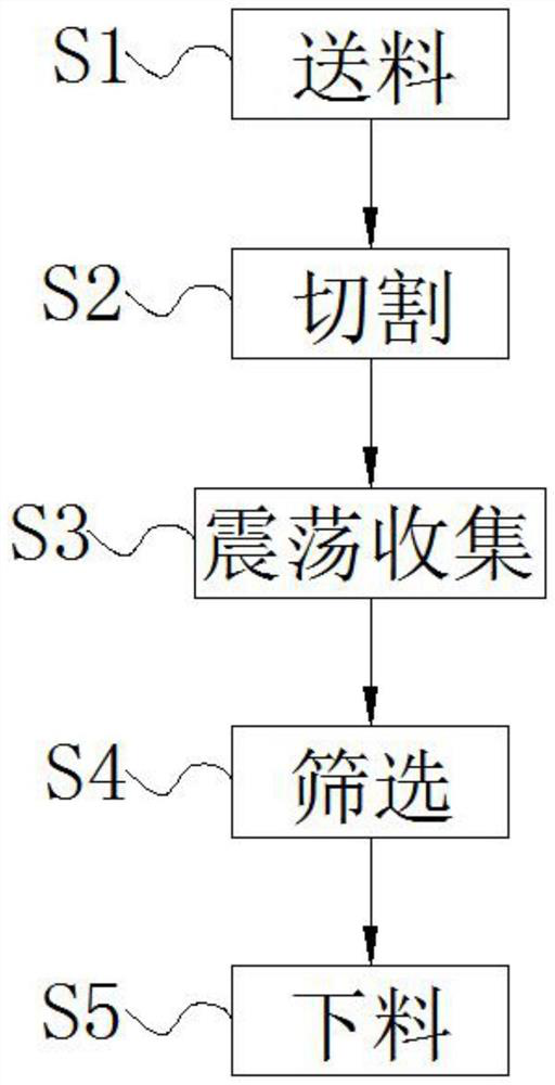
[0026] S1. Feeding: First, the aluminum profile to be cut is transported to the workbench of the cutting station through the conveying equipment, and the aluminum profile to be cut is clamped by the clamp on the workbench;

[0027] S2. Cutting: Start the cutting equipment to lower the knife, and cut the aluminum profile clamped on the workbench according to the required cutting requirements;

[0028] S3. Oscillation collection: the waste slag generated by cutting in step S2 will fall into the collection bucket. At this time, start the vibration mechanism to push the top of the collection bucket, and then cooperate with the buffer reset component to realize the reciprocating vibration treatment of the collection bucket. The vibration mechanism includes a vibration motor, The oscillating cam and the arc-shaped top block adapted to the oscillating cam, the oscillating motor is fixedly installed inside the cutting equipment through a fixing piece, and the output shaft of the oscill...

Embodiment 2

[0032] S1. Feeding: First, the aluminum profile to be cut is transported to the workbench of the cutting station through the conveying equipment, and the aluminum profile to be cut is clamped by the clamp on the workbench;

[0033] S2. Cutting: Start the cutting equipment to lower the knife, and cut the aluminum profile clamped on the workbench according to the required cutting requirements;

[0034]S3. Oscillation collection: the waste slag generated by cutting in step S2 will fall into the collection bucket. At this time, start the vibration mechanism to push the top of the collection bucket, and then cooperate with the buffer reset component to realize the reciprocating vibration treatment of the collection bucket. The vibration mechanism includes a vibration motor, The oscillating cam and the arc-shaped top block adapted to the oscillating cam, the oscillating motor is fixedly installed inside the cutting equipment through a fixing piece, and the output shaft of the oscilla...

Embodiment 3

[0038] S1. Feeding: First, the aluminum profile to be cut is transported to the workbench of the cutting station through the conveying equipment, and the aluminum profile to be cut is clamped by the clamp on the workbench;

[0039] S2. Cutting: Start the cutting equipment to lower the knife, and cut the aluminum profile clamped on the workbench according to the required cutting requirements;

[0040] S3. Oscillation collection: the waste slag generated by cutting in step S2 will fall into the collection bucket. At this time, start the vibration mechanism to push the top of the collection bucket, and then cooperate with the buffer reset component to realize the reciprocating vibration treatment of the collection bucket. The vibration mechanism includes a vibration motor, The oscillating cam and the arc-shaped top block adapted to the oscillating cam, the oscillating motor is fixedly installed inside the cutting equipment through a fixing piece, and the output shaft of the oscill...


PUM


Abstract

The invention discloses a collection type aluminum profile cutting process which specifically comprises the following steps: S1, feeding: firstly, conveying an aluminum profile to be cut to a workbench of a cutting station through conveying equipment, and clamping the aluminum profile to be cut through a clamp on the workbench; S2, cutting, S3, vibration collection, S4, screening and S5, discharging. The invention relates to the technical field of aluminum material machining. According to the invention, it can be guaranteed that waste residues can be completely oscillated to fall into collection equipment through oscillation design in the waste hopper, the purpose of rapidly and conveniently collecting the waste in a centralized mode is well achieved, and the situation that the waste blocks a hopper opening in the continuous cutting working process and collection of the waste is affected is avoided. And meanwhile, in the collecting process, the waste materials can be directly screened, waste residues of different sizes are collected, later recycling is facilitated, and therefore the purposes of energy conservation and environment protection are achieved.

Description

technical field [0001] The invention relates to the technical field of aluminum material processing, in particular to a collection type aluminum profile cutting process. Background technique [0002] Aluminum products made of aluminum and other alloying elements are usually processed into castings, forgings, foils, plates, strips, tubes, rods, profiles, etc., and then cold-formed, sawed, drilled, assembled, It is made by coloring and other processes. The main metal element is aluminum, and some alloying elements are added to improve the performance of aluminum products. The classification of aluminum products: rolled materials, cast materials, non-heat-treated alloys, pure aluminum alloys, aluminum copper Alloy, aluminum-manganese alloy, aluminum-silicon alloy, aluminum-magnesium alloy, aluminum-magnesium-silicon alloy, aluminum-zinc-magnesium alloy, aluminum and other elemental alloys, classification of aluminum processing technology: casting materials, heat-treated alloys,...

Claims


Application Information

Patent Timeline
IPC IPC(8): B23Q11/00B07B1/28B07B1/04
CPCB23Q11/0042B07B1/28B07B1/04
Inventor 罗克众
Owner 湖北基特尔电气成套设备有限公司
Learn More