
Automatic treatment device for oiling test waste liquid

An automatic treatment and waste liquid treatment technology, which is applied in the direction of oxidation water/sewage treatment, sterilization/microdynamic water/sewage treatment, filtration treatment, etc., can solve the problems of oily test waste liquid pollution diffusion and difficult storage

Active Publication Date: 2021-04-30
广西电网有限责任公司桂林供电局
View PDF16 Cites 0 Cited by
  • Summary
  • Abstract
  • Description
  • Claims
  • Application Information

AI Technical Summary

Problems solved by technology

[0002] In recent years, with the continuous development of my country's electric power industry, insulating oil has been widely used in power facilities. The insulation and cooling of high-voltage power facilities are mainly realized by insulating oil for electric power. The detection of power oil quality indicators is a necessary measure to ensure the safe operation of power facilities; however, a small amount of mixed oily test waste liquid containing grease, ethanol, petroleum ether and some chemical reagents will be produced during the detection process of electric power oil. The test waste liquid treatment method generally chooses appropriate storage and centralized treatment. However, due to the uncertainty of the centralized treatment of oily test waste liquid, there is a problem of difficulty in storage and storage, and improper centralized treatment may easily lead to oily test waste liquid. Diffusion of pollution has certain disadvantages

Method used


Image

  • Automatic treatment device for oiling test waste liquid

Examples


Embodiment Construction

[0030] The following will clearly and completely describe the technical solutions in the embodiments of the present invention with reference to the accompanying drawings in the embodiments of the present invention. Obviously, the described embodiments are only some, not all, embodiments of the present invention. Based on the embodiments of the present invention, all other embodiments obtained by persons of ordinary skill in the art without creative efforts fall within the protection scope of the present invention.

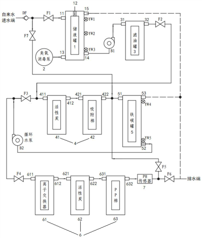
[0031] figure 1 It is a schematic diagram of the composition and connection of the automatic processing device in the embodiment of the present invention.

[0032] An embodiment of the present invention provides an automatic treatment device for oily test waste liquid. The automatic treatment device includes a liquid storage tank 1, an ozone disinfection pump 2, an oil filter tank 3, a secondary waste liquid treatment system 4, and an iron carbon tank 5. Tertiary ...


PUM


Abstract

The invention discloses an automatic treatment device for an oiling test waste liquid. The automatic treatment device comprises a liquid storage tank, an ozone disinfection pump, an oil filtering tank, a secondary waste liquid treatment system, an iron-carbon tank, a tertiary waste liquid treatment system and a pH sensor; a tap water inlet end is respectively communicated with a water inlet of the liquid storage tank and a liquid inlet of the iron-carbon tank; the ozone disinfection pump is communicated with a disinfection port; a liquid outlet of the liquid storage tank is communicated with a liquid inlet of the oil filtering tank; a liquid outlet of the oil filtering tank is communicated with a secondary waste liquid treatment inlet; a secondary waste liquid treatment outlet is communicated with a liquid inlet of the iron-carbon tank; a liquid outlet of the iron-carbon tank is respectively communicated with the secondary waste liquid treatment inlet and a ternary waste liquid treatment inlet; and a ternary waste liquid treatment outlet is respectively communicated with a liquid inlet and a drainage end of the iron-carbon tank through a pH sensor. In the embodiment of the invention, the automatic treatment device can timely, efficiently and automatically treat the oiling test waste liquid generated in the electric power oil detection process, the oiling test waste liquid does not need to be stored, and the pollution diffusion of the oiling test waste liquid can be effectively avoided.

Description

technical field [0001] The invention relates to the technical field of waste liquid treatment devices, in particular to an automatic treatment device for oily test waste liquid. Background technique [0002] In recent years, with the continuous development of my country's electric power industry, insulating oil has been widely used in power facilities. The insulation and cooling of high-voltage power facilities are mainly realized by insulating oil for electric power. The detection of power oil quality indicators is a necessary measure to ensure the safe operation of power facilities; however, a small amount of mixed oily test waste liquid containing grease, ethanol, petroleum ether and some chemical reagents will be produced during the detection process of electric power oil. The test waste liquid treatment method generally chooses appropriate storage and centralized treatment. However, due to the uncertainty of the centralized treatment of oily test waste liquid, there is a ...

Claims


Application Information

Patent Timeline
IPC IPC(8): C02F9/06
CPCC02F9/00C02F1/78C02F1/50C02F1/001C02F1/283C02F1/285C02F1/46176C02F1/42C02F2301/08C02F2201/002C02F2201/004C02F2201/005C02F2209/06C02F2209/42C02F2303/14
Inventor 梁求发周雄王伟杨胜雄孙春树刘育鑫李青邹利林
Owner 广西电网有限责任公司桂林供电局
Learn More