Efficient textile dedusting and disinfecting device

A technology for disinfection devices and textiles, applied in the field of textiles, can solve problems such as the occurrence of peculiar smell in textiles and disinfection devices, and achieve the effects of improving disinfection efficiency, ensuring a normal disinfection environment, and prolonging the service life

Inactive Publication Date: 2021-04-30
李国朋
View PDF1 Cites 1 Cited by
  • Summary
  • Abstract
  • Description
  • Claims
  • Application Information

AI Technical Summary

Problems solved by technology

[0007] Aiming at the deficiencies of the prior art, the present invention provides a high-efficiency dedusting and disinfection device for textiles, which solves the problem that the dis

Method used


Image

  • Efficient textile dedusting and disinfecting device
  • Efficient textile dedusting and disinfecting device
  • Efficient textile dedusting and disinfecting device

Examples


Example Embodiment

[0034] Embodiment one:

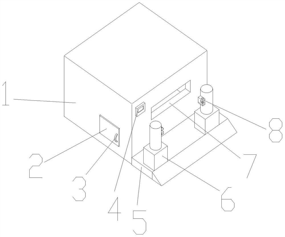
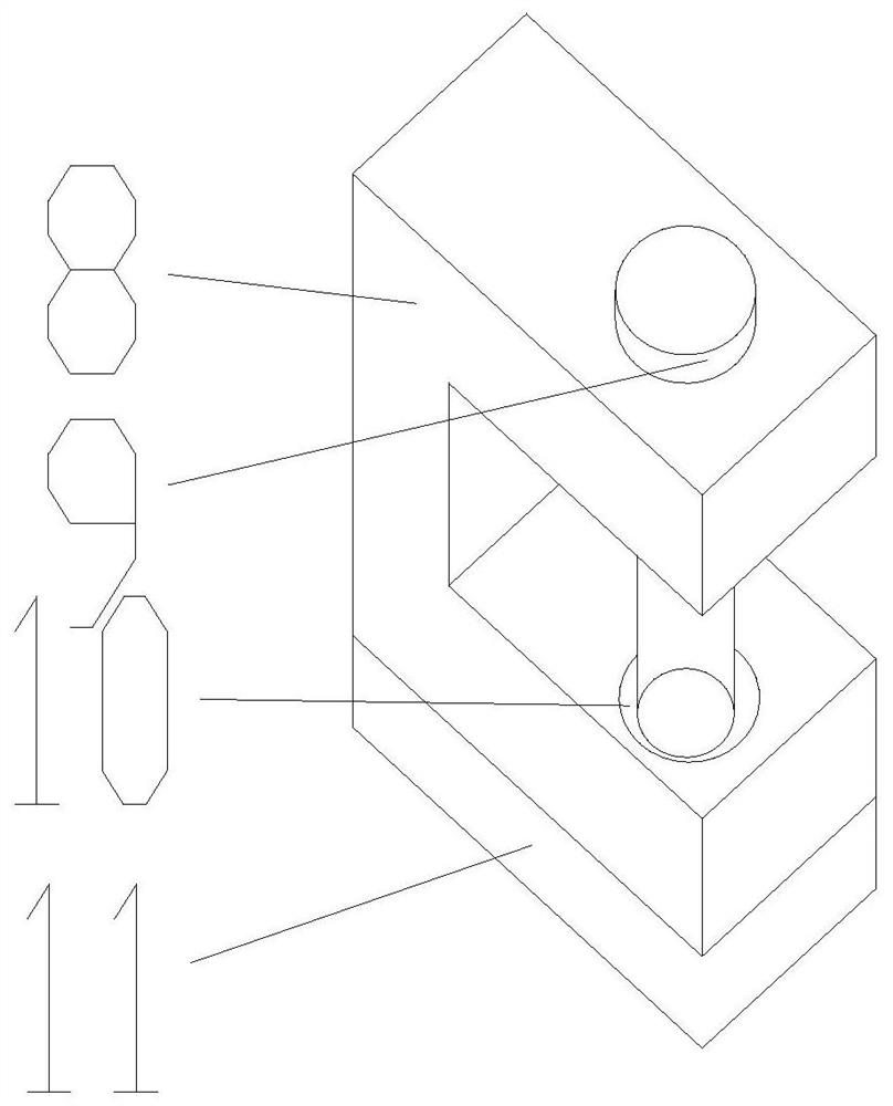
[0035] like Figure 1-2 , the present invention provides a technical solution: a high-efficiency dedusting and disinfection device for textiles, comprising a box body 1, the front middle part of the box body 1 is provided with a feeding port 7, and the front side of the box body 1 is located at the upper left side of the side of the feeding port 7 The controller 4 is fixedly connected, the front bottom of the box body 1 is fixedly connected with the bottom plate 5, the top and both sides of the bottom plate 5 are fixedly connected with the feeder 6, and the top of the feeder 6 is fixedly connected with the U Type clamping block 8, the left bottom position of box body 1 is provided with box door 2 near the position of bottom plate 5, and the front right middle part position of box door 2 is fixedly connected with handle 3.

[0036] Wherein, the bottom of the U-shaped clamping block 8 is fixedly connected with the limit block 11, and the top of the U-sh...

Example Embodiment

[0038] Embodiment two:

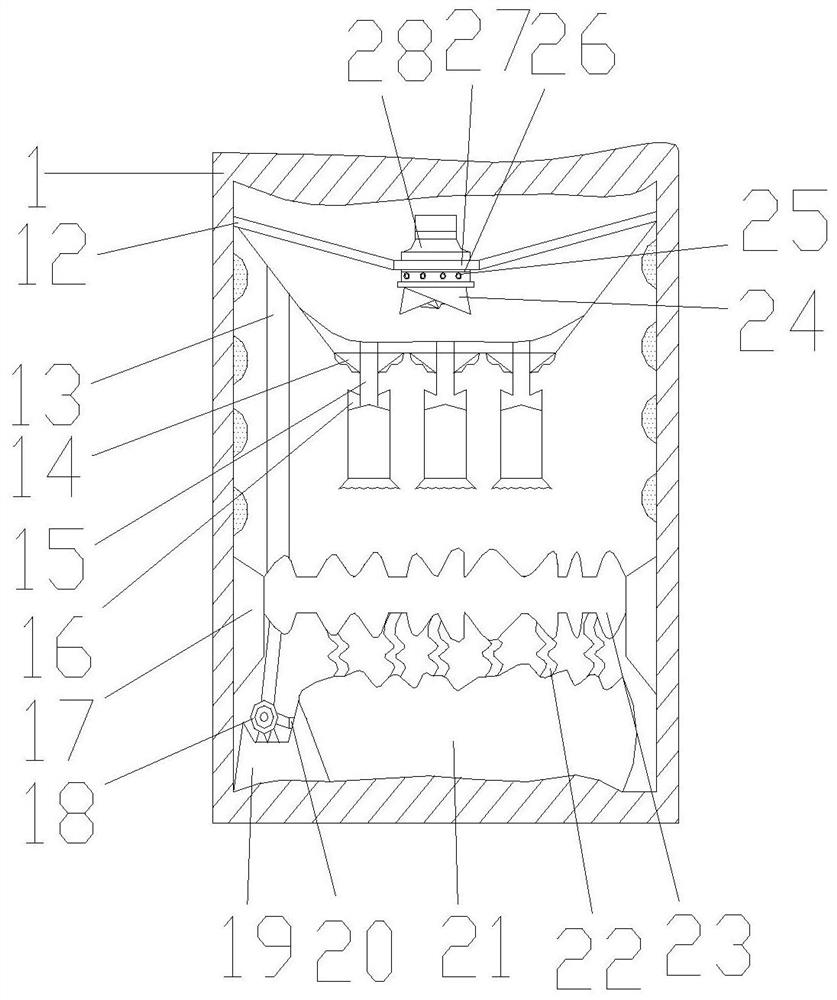
[0039] like Figure 1-3 As shown, on the basis of Embodiment 1, the present invention provides a technical solution: a transition box 12 is fixedly connected to the top of the inner wall on both sides of the box body 1, and a delivery pipe 13 is arranged on the left side of the bottom of the transition box 12, and the transition box 12 The top middle position of the top is fixedly connected with a connecting piece 27, and the bottom of the connecting piece 27 is fixedly connected with a feeding tray 24, and the connecting piece 27 is provided with a sealing ring 26 between the feeding trays 24, and the top outer surface of the feeding tray 24 is provided with a fixed The screw 25 and the top of the connector 27 are fixedly connected with the bearing 28, the top of the bearing 28 communicates with the conveying pipe 13, the bottom of the transition box 12 communicates with the telescopic vacuum cleaner 15, and the bottom of the transition box 12 is locate...

Example Embodiment

[0041] Embodiment three:

[0042] like Figure 1-5 As shown, on the basis of Embodiment 1 and Embodiment 2, the present invention provides a technical solution: the top of the back of the inner cavity of the box body 1 is provided with a vent 29, and the inside of the vent 29 is provided with a cooling fan 30, and the box body The inner walls on both sides of 1 are located below the vent 29 and are fixedly connected with a fixed frame 31, and the side of the fixed frame 31 away from the vent 29 is fixedly connected with a disinfection device 32, and the middle position of the back of the inner cavity of the box body 1 is provided with a discharge port 33 The inner walls on both sides of the box body 1 are fixedly connected with a sealing layer 34 under the fixed frame 31, the bottom of the inner cavity of the box body 1 is fixedly connected with a support seat 36, and the top of the support seat 36 is fixedly connected with a balloon removal layer 35.

[0043] Wherein, the di...


PUM


Abstract

The invention discloses an efficient textile dedusting and disinfecting device. The efficient textile dedusting and disinfecting device comprises a box body; a feeding port is formed in the middle of the front face of the box body; a controller is fixedly connected to the upper left portion, located on one side of the feeding port, of the front face of the box body; a bottom plate is fixedly connected to the bottom of the front face of the box body; feeders are fixedly connected to the two sides of the top of the bottom plate; a U-shaped clamping block is fixedly connected to the position, close to the feeding port, of the top of each feeder; a box door is arranged at the position, close to the bottom plate, of the bottom of the left side of the box body; and a handle is fixedly connected to the middle of the right side of the front face of the box door. The invention relates to the field of spinning. The efficient textile dedusting and disinfecting device can effectively collect and treat dust, conveniently protect the interior cleanness, effectively reduce the interior temperature, achieve the heat dissipation effect, prolong the service life of the device and protect the device, and the disinfection device disinfect the textiles, the normal disinfection environment of the textiles is guaranteed, and the disinfection efficiency is improved.

Description

technical field [0001] The invention relates to the technical field of textiles, in particular to a high-efficiency dedusting and disinfection device for textiles. Background technique [0002] The original meaning of textile is taken from the general term of spinning and weaving, but with the continuous development and improvement of the textile knowledge system and subject system, especially after the emergence of non-woven textile materials and three-dimensional composite weaving technologies, the current textile is not only a traditional Hand spinning and weaving also include garment, industrial and decorative textiles produced by non-woven technology, modern three-dimensional weaving technology, and modern electrostatic nano-netting technology. Therefore, modern textile refers to a multi-scale structure processing technology of fibers or fiber aggregates. Ancient Chinese textile and printing and dyeing technology has a very long history. As early as the primitive socie...

Claims


Application Information

Patent Timeline
IPC IPC(8): D06G1/00A61L2/20A61L2/26A61L101/10
CPCA61L2/202A61L2/26A61L2202/26D06G1/00
Inventor 李国朋申翱
Owner 李国朋
Why Eureka
Try Eureka