Design method of muffle furnace heating system

A heating system and design method technology, applied in computer-aided design, design optimization/simulation, calculation, etc., can solve problems that consume a lot of time, manpower, and material resources, and achieve the effect of saving time

Pending Publication Date: 2021-04-30
IRICO DISPLAY DEVICES
View PDF0 Cites 0 Cited by
  • Summary
  • Abstract
  • Description
  • Claims
  • Application Information

AI Technical Summary

Problems solved by technology

After the size of the muffle furnace becomes larger, how to adjust the heating system in the furnace to adapt to the new muffle furnace structure is a current problem. Now through experience and practice, the muffle furnace heating system is constantly adjusted to adapt to the new muffle furnace structure. It takes a lot of time, manpower and material resources

Method used


Image

  • Design method of muffle furnace heating system
  • Design method of muffle furnace heating system

Examples


Embodiment Construction

[0033] The present invention will be further described in detail below in conjunction with specific embodiments, which are explanations of the present invention rather than limitations.

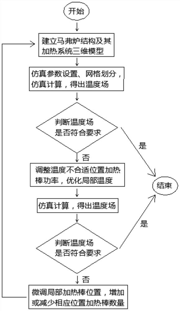
[0034] Such as figure 1 Shown, the design method of muffle furnace heating system of the present invention comprises the following steps:

[0035] Step 1. Based on the muffle furnace structure and heating system of the existing liquid crystal glass production line, adjust the heating system appropriately according to the size change of the muffle furnace;

[0036] Step 2, using Croe 3D modeling software to establish a simulation model of the muffle furnace and its heating system.

[0037] Step 3, import the simulation model into the FloEFD thermal simulation software for simulation parameter setting, grid division, and then perform simulation numerical calculation to obtain the simulation calculation result, that is, the temperature field distribution inside the entire muffle furnace.

[00...


PUM


Abstract

The invention discloses a design method of a muffle furnace heating system. The design method comprises the steps of 1, designing an initial heating system based on the structure of a muffle furnace; 2, establishing simulation models of the muffle furnace and the heating system; 3, performing simulation numerical calculation according to the simulation models; 4, judging whether the heating system meets the requirement or not according to a simulation calculation result, and if the requirement is met, ending the design task; if not, entering the step 5; 5, adjusting the power of the heating rod at the position with the improper temperature, and calculating a simulation numerical value; 6, judging whether the heating system meets the requirement or not according to the simulation calculation result obtained in the step 5, and if the requirement is met, ending the design task; if not, entering the step 7; 7, finely adjusting the positions of the heating rods at the inappropriate temperature positions and / or changing the number of the heating rods at the corresponding positions; and 8, returning to the step 2. Optimization and improvement of the muffle furnace heating system can be quickly achieved, and time, manpower and material resources are greatly saved.

Description

technical field [0001] The invention belongs to the field of substrate glass manufacturing and relates to a design method of a muffle furnace heating system. Background technique [0002] The pool furnace melts a certain proportion of batch materials, and the melted glass goes through a series of processes in the channel, and then introduces the glass liquid into the muffle furnace through the feeding tank. The muffle furnace is the key position to determine whether the glass can be formed. Here, overflow bricks, edge pulling machines and other structures are used to make the glass liquid overflow and pull down to form. Therefore, the temperature in the furnace is particularly important, and both the horizontal and vertical directions must comply with the specified temperature gradient. [0003] However, with the continuous development of the liquid crystal glass industry, larger and thinner glass needs to be produced, and the muffle furnace and its internal equipment must ...

Claims


Application Information

Patent Timeline
Patent Type & Authority Applications(China)
IPC IPC(8): G06F30/20G06F113/08G06F119/08
CPCG06F30/20G06F2113/08G06F2119/08
Inventor 李淼王涛徐莉华王答成张栋汪彬彬
Owner IRICO DISPLAY DEVICES
Why Eureka
Try Eureka