A Method for Image Recognition of Closing Faults of Truncated Plug Door Handle
An image recognition and handle technology, applied in character and pattern recognition, instruments, calculations, etc., can solve problems such as low detection efficiency and easy fatigue, and achieve the effect of improving accuracy, saving time, and meeting real-time requirements.
- Summary
- Abstract
- Description
- Claims
- Application Information
AI Technical Summary
Problems solved by technology
Method used
Image
Examples
specific Embodiment approach 1
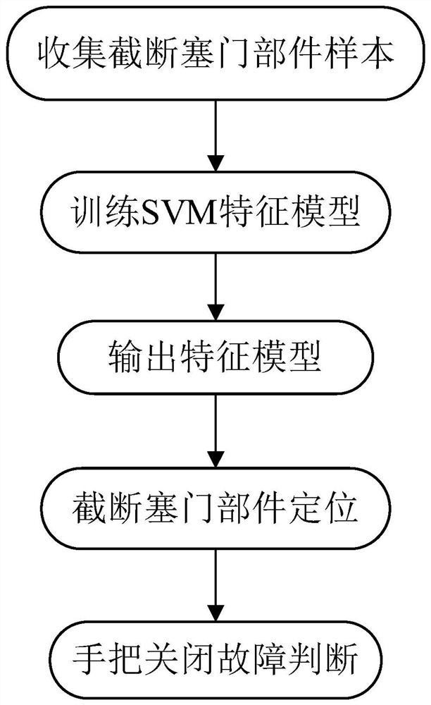
[0035] Specific implementation mode one: combine figure 1 This embodiment is described. In this embodiment, a fault image recognition method for closing a truncation plug handle includes:
[0036] Step 1. Obtain the truncated plug part image and the image not containing the truncated plug part, take the truncated plug part image as a positive sample, and mark it as 1, and the image that does not contain the truncated plug part as a negative sample, mark it as 0, and set The positive and negative samples and corresponding labeled files are divided into training set and test set;
[0037] Step 2, normalize the training set in step 1, and extract the HOG feature vector of the normalized training set; input the extracted HOG feature vector into the SVM linear classifier, and use the SVM linear classification The device trains the feature model of the truncated plug door part;
[0038] Step 3, determine whether there is a truncated plug part in the truck to be detected, if it exi...
specific Embodiment approach 2
[0051] Specific implementation mode two: the difference between this implementation mode and specific implementation mode one is that step three also includes:
[0052] When the number of sub-image blocks recorded as 1 exceeds half of the total number of image blocks, the gradient in the horizontal direction of the sub-image at the handle position is further calculated to obtain a gradient map in the horizontal direction. The gradient map is as follows Image 6 As shown on the left, and calculate the coordinate points of the upper boundary and the lower boundary of the gradient map, respectively constitute the set of coordinate points of the upper boundary and the set of coordinate points of the lower boundary; a straight line, such as Image 6 As shown on the right; if there are double lines, it is considered that there is an upper and lower boundary contour of the handle, and the angle between the two straight lines is calculated. If the angle is within the angle threshold r...
specific Embodiment approach 3
[0056] Specific embodiment three: the difference between this embodiment and specific embodiment one or two is that step three also includes:
[0057] If the two straight lines do not exist completely or the angle between the two straight lines is not within the angle threshold range, then there is no upper and lower boundary contour of the handle, and then the handle position sub-image is binarized to calculate the maximum connected area of the binary image , the largest connected region such as Figure 7 As shown; set the range of handle structure characteristic parameters according to the maximum connected area; satisfy the range of handle structure characteristic parameters of the outer contour of the maximum connected area, then there is a handle, which is the handle closing fault; if the handle structure characteristic parameters are not satisfied range, there is no handle, which is normal.
[0058] In practice, in order to identify the handlebar closing fault more co...
PUM
 Abstract
Description
Claims
Application Information
 - R&D
- Intellectual Property
- Life Sciences
- Materials
- Tech Scout
- Unparalleled Data Quality
- Higher Quality Content
- 60% Fewer Hallucinations
Browse by: Latest US Patents, China's latest patents, Technical Efficacy Thesaurus, Application Domain, Technology Topic, Popular Technical Reports.
© 2025 PatSnap. All rights reserved.Legal|Privacy policy|Modern Slavery Act Transparency Statement|Sitemap|About US| Contact US: help@patsnap.com


