Heat-conducting furnace tube for two-stroke radiation section ethylene cracking furnace as well as preparation method and application of heat conduction furnace tube

A technology of ethylene cracking furnace and heat conduction furnace, which is applied in the direction of hydrocarbon cracking, cracking, non-catalytic thermal cracking, etc., can solve the problems of poor heat transfer effect, prolonged operation period, easy coking and carburizing, etc., and reduce the amount of coking. , Improve heat transfer performance, reduce the effect of carburization

Active Publication Date: 2021-05-04
CHINA PETROLEUM & CHEM CORP +1
View PDF6 Cites 0 Cited by
  • Summary
  • Abstract
  • Description
  • Claims
  • Application Information

AI Technical Summary

Problems solved by technology

[0008] The purpose of the present invention is to provide a kind of heat-conducting furnace tube for ethylene cracking furnace in two-pass radiation section, its preparation method and Applied in the cracking furnace, the heat conduction furnace tube has a good heat transfer effect, which significantly increases the heat transfer enhancement comprehensive factor of the heat conduction furnace tube by 15-27%, and can effectively reduce the coking amount and carburization of the heat conduction furnace tube. Extended operating cycle

Method used


Image

  • Heat-conducting furnace tube for two-stroke radiation section ethylene cracking furnace as well as preparation method and application of heat conduction furnace tube
  • Heat-conducting furnace tube for two-stroke radiation section ethylene cracking furnace as well as preparation method and application of heat conduction furnace tube
  • Heat-conducting furnace tube for two-stroke radiation section ethylene cracking furnace as well as preparation method and application of heat conduction furnace tube

Examples


preparation example Construction

[0044] Preferably, the preparation method of the reinforced coating includes: mixing raw materials with water to form a slurry, spraying it on the surface of the heat conducting layer, and then sintering at a temperature of 1000-1100°C to form a reinforced coating;

[0045] Based on the total weight of the strengthening coating, the strengthening coating includes SiO in weight percentage 2 45-80% by weight, K 2 O 10-25% by weight, Al 2 o 3 0-10% by weight, MgO 0-10% by weight, ZnO 0-20% by weight, Co 3 o 4 0-5% by weight, Na 2 O 0-10% by weight.

[0046] According to the above method, a reinforcing coating is provided on the surface of the heat conducting layer to reduce the interface thermal resistance between the heat conducting layer and the reinforcing coating, improve the heat transfer performance of the heat conducting furnace tube, and effectively reduce the amount of coking on the inner wall of the heat conducting furnace tube.

[0047] The third aspect of the ...

Embodiment 1

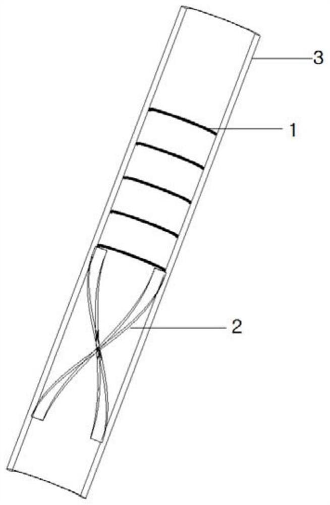
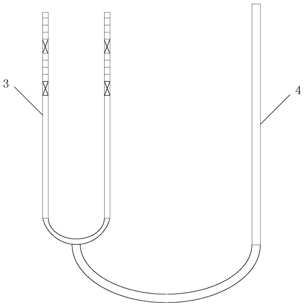
[0059] This embodiment is used to provide a heat conduction furnace tube, such as figure 2 As shown, it is a two-pass radiant section cracking furnace tube comprising a first-pass furnace tube 3 and a second-pass furnace tube 4 .

[0060] The inner diameter of the main body of the furnace tube D = 50mm, the length of the main body of the furnace tube L = 13m, such as figure 2 As shown, 8 sets of heat conducting members are evenly arranged on the two ends of the U-shaped tube along the axial direction of the furnace tube, and the extension length of the 8 sets of heat conducting members along the axial direction of the main body of the furnace tube is H=4m.

[0061] The first heat conduction element 1 is a circular ring formed around the cross-section of the inner wall of the main body of the furnace tube, and the diameter d of the inner ring of the first heat conduction element 1 is 12.5mm. A set of heat conduction members includes 15 first heat conduction elements 1 , and ...

Embodiment 2

[0066] This embodiment is used to provide a heat conduction furnace tube, such as figure 2 As shown, it is a two-pass radiant section cracking furnace tube comprising a first-pass furnace tube 3 and a second-pass furnace tube 4 .

[0067] The inner diameter of the main body of the furnace tube D = 50mm, the length of the main body of the furnace tube L = 13m, such as figure 2 As shown, 8 sets of heat conducting members are evenly arranged on the two ends of the U-shaped tube along the axial direction of the furnace tube, and the extension length of the 8 sets of heat conducting members along the axial direction of the main body of the furnace tube is H=4m.

[0068] The first heat conduction element 1 is a circular ring formed around the cross-section of the inner wall of the main body of the furnace tube, and the diameter d of the inner ring of the first heat conduction element 1 is 12.5mm. A set of heat conduction members includes 15 first heat conduction elements 1 , and ...


PUM

PropertyMeasurementUnit
thicknessaaaaaaaaaa
thicknessaaaaaaaaaa
thicknessaaaaaaaaaa

Abstract

The invention relates to the field of heat-conducting furnace tubes for ethylene cracking furnaces, and discloses a heat-conducting furnace tube for a two-stroke radiation section ethylene cracking furnace, a preparation method of the heat-conducting furnace tube and an application of the heat-conducting furnace tube in a cracking furnace. The heat-conducting furnace tube comprises a furnace tube main body, wherein multiple groups of heat-conducting components are sequentially and repeatedly arranged on the inner side wall of the furnace tube main body in the length direction of the furnace tube main body; first heat conduction pieces and second heat conduction pieces, wherein the multiple first heat conduction pieces are arranged, surround the cross section of the inner side wall of the furnace tube body by a circle and are formed by protruding towards the interior of the furnace tube body; and the second heat conduction piece is spirally arranged along the axial direction of the furnace tube main body. The heat-conducting furnace tube has a good heat transfer effect, the heat transfer strengthening comprehensive factor of the heat-conducting furnace tube is remarkably improved by 15-27%, and meanwhile the coking amount and the carburization phenomenon of the heat-conducting furnace tube can be effectively reduced.

Description

technical field [0001] The invention relates to the field of heat-conducting furnace tubes for ethylene cracking furnaces, in particular to a heat-conducting furnace tube for a two-pass radiation section ethylene cracking furnace, a preparation method thereof, and an application thereof in cracking furnaces. Background technique [0002] At present, the industrial production of ethylene mainly adopts the method of pyrolysis of high-temperature steam in a tubular reactor. For cracking furnaces producing ethylene, in order to improve the selectivity of cracking products, the yield of cracking products and the adaptability to raw materials, it is necessary to optimize the structure of the cracking furnace, especially the structure of the radiant furnace tube of the cracking furnace. In recent years, a variety of radiant coils with different structures have appeared, mainly including single-row branch reducers, mixed-row branch reducers, non-branch reducers, and single-pass equa...

Claims


Application Information

Patent Timeline
Patent Type & Authority Applications(China)
IPC IPC(8): C10G9/20C10G9/16C07C4/04C07C11/04C22C30/00C04B35/14C04B35/622
CPCC10G9/20C10G9/16C07C4/04C22C27/06C22C30/00C04B35/14C04B35/62222C10G2400/20C04B2235/3201C04B2235/3206C04B2235/3217C04B2235/3284C04B2235/3277C04B2235/656C07C11/04Y02P20/10
Inventor 刘俊杰杨士芳王国清张利军周丛张兆斌杜志国李晓锋杨沙沙郭莹
Owner CHINA PETROLEUM & CHEM CORP
Why Eureka
Try Eureka