High-precision large-pressure-reduction-ratio automatic pressure-regulating gas pressure-stabilizing and pressure-reducing combined valve

A technology of automatic pressure regulation and gas pressure stabilization, which is applied in the direction of the valve's device for absorbing fluid energy, device for pressure relief on the sealing surface, valve lift, etc., which can solve the problem of high cost, complex system, upstream and downstream anti-interference Poor ability and other problems, to achieve the effect of improving the ability to resist pressure

Active Publication Date: 2021-05-04
BEIJING SATELLITE MFG FACTORY
View PDF6 Cites 5 Cited by
  • Summary
  • Abstract
  • Description
  • Claims
  • Application Information

AI Technical Summary

Problems solved by technology

[0002] At present, the fuel cell gas supply system mostly adopts two methods: mechanical pressure regulating valve and pneumatic pressure regulating. When the pressure changes during the use of mechanical pressure regulating, the operator needs to manually adjust, or the method of predetermined adjustment is adopted. However, this method is harmful to the above Downstream anti-interference ability is poor
Pneumatic pressure regulation often requires an additional auxiliary air source for pressure control, the system is complex, and the cost is high. At the same time, because of the addition of an additional auxiliary air source system for control, the response speed of its pressure will inevitably be reduced, and the reliability of the system will also be greatly improved. reduce

Method used


Image

  • High-precision large-pressure-reduction-ratio automatic pressure-regulating gas pressure-stabilizing and pressure-reducing combined valve
  • High-precision large-pressure-reduction-ratio automatic pressure-regulating gas pressure-stabilizing and pressure-reducing combined valve
  • High-precision large-pressure-reduction-ratio automatic pressure-regulating gas pressure-stabilizing and pressure-reducing combined valve

Examples


Embodiment Construction

[0042] The present invention will be further elaborated below in conjunction with the accompanying drawings.

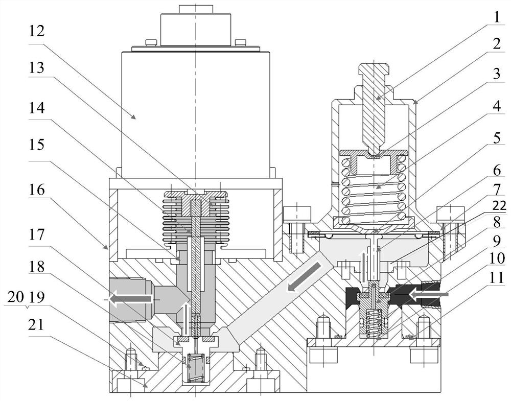
[0043] The present invention consists of figure 1 As shown, the integrated design is adopted, and all parts are installed on the substrate to form a highly integrated valve group.

[0044] The primary valve assembly 8 is in the form of vulcanized rubber, and the fluorine rubber is vulcanized on the metal frame. The primary valve assembly 8 adopts a reverse unloading structure, and a cylindrical stepped cavity is processed inside, and the diameter of the upper cylindrical cavity is smaller than that of the lower end. The diameter of the cylindrical cavity is 0.8-1.1mm, and two oblique holes are opened at the boss on the top of the first-stage valve assembly. The diameter of the oblique holes is 0.5-0.8mm. The cylindrical stepped cavity in the direction runs through each other.

[0045] The primary valve assembly 8 has a sealing groove on the outer surface, and a seal...


PUM

PropertyMeasurementUnit
diameteraaaaaaaaaa
heightaaaaaaaaaa
thicknessaaaaaaaaaa

Abstract

The invention relates to a high-precision large-pressure-reduction-ratio automatic pressure-regulating gas pressure-stabilizing and pressure-reducing combined valve. A two-stage pressure-reducing structure is adopted, and high-precision output of pressure is achieved. A mechanical pressure-reducing valve is adopted for the first stage, and an electrical proportional pressure-reducing valve is adopted for the second stage. A reverse unloading type main body structure is adopted for the first-stage pressure-reducing valve, the pressure force of falling-in opening pressure acting on a valve is balanced, and thus the influence of gas source pressure fluctuation is reduced; and for the problem of high upstream pressure, a metal diaphragm type structure is adopted for the first-stage pressure-reducing valve, and thus the pressure resistance is improved. A main body form of an electromagnetic proportional valve is adopted for the second-stage pressure-reducing valve, a reverse unloading type structure is adopted for a valve body, and thus interference of inlet pressure is further reduced; and meanwhile, a driving element of a proportional electromagnet is adopted, and thus the stability of output pressure is ensured on the premise of ensuring the flow.

Description

technical field [0001] The invention belongs to the field of industrial valve design, and relates to a high-precision and large pressure-reducing ratio automatic pressure-regulating gas pressure-stabilizing and pressure-reducing combined valve. Background technique [0002] At present, fuel cell gas supply systems mostly use mechanical pressure regulating valves and pneumatic pressure regulating methods. When mechanical pressure regulation changes pressure during use, the operator needs to manually adjust it, or use a pre-set adjustment method, but this method is harmful to the above. The downstream anti-interference ability is poor. Pneumatic pressure regulation often requires an additional auxiliary air source for pressure control, the system is complex, and the cost is high. At the same time, because of the addition of an additional auxiliary air source system for control, the response speed of the pressure will inevitably decrease, and the reliability of the system will ...

Claims


Application Information

Patent Timeline
Patent Type & Authority Applications(China)
IPC IPC(8): F16K17/32F16K1/44F16K1/48F16K31/126F16K31/06F16K39/02F16K47/08F16K27/02F16K27/08H01M8/04089
CPCF16K17/32F16K1/44F16K1/48F16K31/1262F16K31/126F16K31/0675F16K39/02F16K47/08F16K27/02F16K27/08H01M8/04089Y02E60/50
Inventor 赵健谢文何通刘建峰刘畅李磊磊
Owner BEIJING SATELLITE MFG FACTORY
Why Eureka
Try Eureka