
Display substrate, display panel and display device

A technology for display substrates and display areas, applied in instruments, semiconductor devices, optics, etc., can solve the problems of different surface roughness, poor area binding, failure, etc. in the binding area, so as to improve process stability and improve production yield , The effect of balancing the surface roughness

Active Publication Date: 2021-05-04
HUBEI YANGTZE IND INNOVAION CENT OF ADVANCED DISPLAY CO LTD
View PDF7 Cites 5 Cited by
  • Summary
  • Abstract
  • Description
  • Claims
  • Application Information

AI Technical Summary

Problems solved by technology

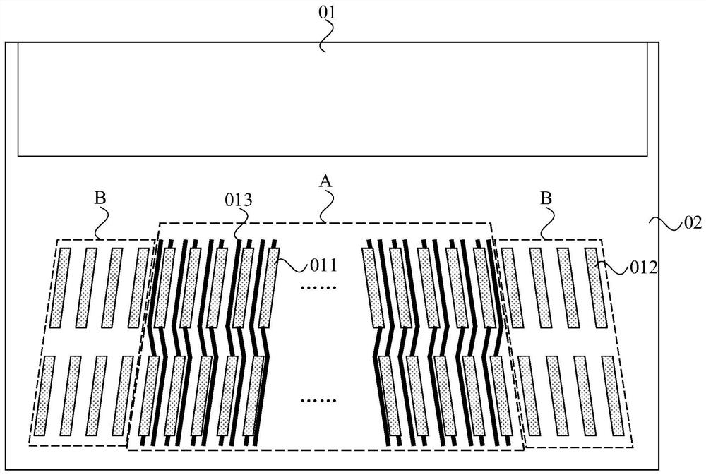
When the resolution of the display panel is high, in order to better match the process and cost, multi-layer pads are usually set for wiring design, that is, pads arranged in an array are set, and dummy pads without signal lines are reserved. , so that the surface roughness of the bonding area is different. When bonding the driver chip, when the same pressure is used, the bonding effect of the driver chip is different, which may lead to poor bonding or even failure in some areas

Method used


Image

  • Display substrate, display panel and display device
  • Display substrate, display panel and display device
  • Display substrate, display panel and display device

Examples


Embodiment Construction

[0032] The present invention will be further described in detail below in conjunction with the accompanying drawings and embodiments. It should be understood that the specific embodiments described here are only used to explain the present invention, but not to limit the present invention. In addition, it should be noted that, for the convenience of description, only some structures related to the present invention are shown in the drawings but not all structures.

[0033] Terms used in the embodiments of the present invention are only for the purpose of describing specific embodiments, and are not intended to limit the present invention. It should be noted that the orientation words such as "up", "down", "left", and "right" described in the embodiments of the present invention are described from the angles shown in the drawings, and should not be interpreted as a reference to the implementation of the present invention. Example limitations. Also in this context, it also nee...


PUM


Abstract

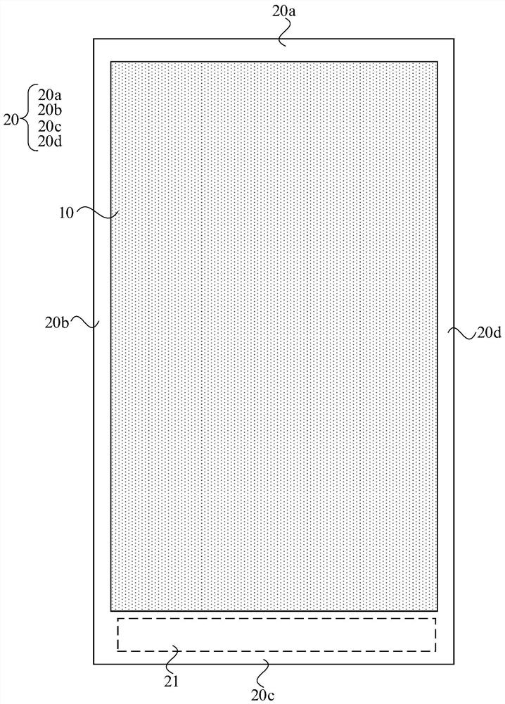
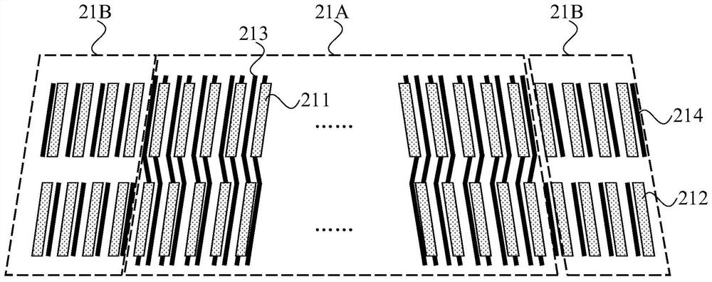
The invention discloses a display substrate, a display panel and a display device. The display substrate comprises a display area and a frame area. The frame area comprises a binding area, the binding area comprises a first area and a second area, the first area comprises a plurality of first bonding pads, the second area comprises a plurality of second bonding pads, the first bonding pads are arranged into a first bonding pad array, and the second bonding pads are arranged into a second bonding pad array; a plurality of first signal lines are electrically connected with the first bonding pads, and at least parts of the first signal lines extend to the position between every two adjacent first bonding pads; the second bonding pads are dummy bonding pads, or a part of the second bonding pads is electrically connected with a second signal line; and the binding area further comprises a plurality of dummy wires, and at least partial areas of the dummy wires are located between every two adjacent first bonding pads, and / or between every two adjacent second bonding pads, and / or between the adjacent first bonding pads and second bonding pads. According to the technical scheme, the process stability in the binding process can be improved, and a preparation yield of the display panel is improved.

Description

technical field [0001] Embodiments of the present invention relate to the field of display technology, and in particular, to a display substrate, a display panel, and a display device. Background technique [0002] With the development of display technology, consumers' requirements for display panels are constantly increasing, and various display panels emerge in an endless stream, such as liquid crystal display panels, organic light-emitting display panels, and the like. [0003] A display panel generally includes a display area and a non-display area. The display area is provided with sub-pixels for displaying images, and the non-display area is provided with structures such as driving circuits for loading display driving signals. In the module process of the display panel, the bonding process is a very important process, and the pins of the driver chip or other functional components are bonded to the pads provided in the non-display area through the bonding process. When...

Claims


Application Information

Patent Timeline
IPC IPC(8): G02F1/1345
CPCG02F1/1345G02F1/13458H10K59/88H10K59/131G02F1/136254G02F1/136286
Inventor 杨春辉
Owner HUBEI YANGTZE IND INNOVAION CENT OF ADVANCED DISPLAY CO LTD
Learn More