Cooking equipment

A technology for cooking equipment and cooking cavity, applied in the field of kitchen utensils, can solve the problems of uneven heating of the cooking cavity 110 ′, oil stains, food residues left, affecting the cooking effect of food, etc., and achieves improved user experience, high cleanliness, improved The effect of reliability

Active Publication Date: 2021-05-07
GUANGDONG MIDEA WHITE HOME APPLIANCE TECH INNOVATION CENT CO LTD +1
View PDF9 Cites 0 Cited by
  • Summary
  • Abstract
  • Description
  • Claims
  • Application Information

AI Technical Summary

Problems solved by technology

like figure 1 and figure 2 As shown, the heat source 140' of the current oven 100' is usually directly built into the upper cavity wall and the lower cavity wall of the cooking cavity 110', so that there will be oil stains and food residues left on the heat source 140' or the heat source 140' during the cooking process. The cavity wall of the nearby cooking cavity 110' is difficult to clean. At the same time, the temperature difference between multiple cavity walls in the cooking cavity 110' is relatively large, and the cooking cavity 110' is unevenly heated, which affects the cooking effect of food.

Method used


Image

  • Cooking equipment
  • Cooking equipment
  • Cooking equipment

Examples


Embodiment 1

[0063] Such as Figure 3 to Figure 22 As shown, according to the first aspect of the present invention, a cooking device 100 is provided, including a cooking cavity 110, a cover plate 120 and a heat source 140, wherein the cover plate 120 is arranged on the inside or outside of the cooking cavity 110, and An accommodating cavity 130 is formed between the cover plate 120 and the cooking cavity 110 ; the heat source 140 is disposed in the accommodating cavity 130 .

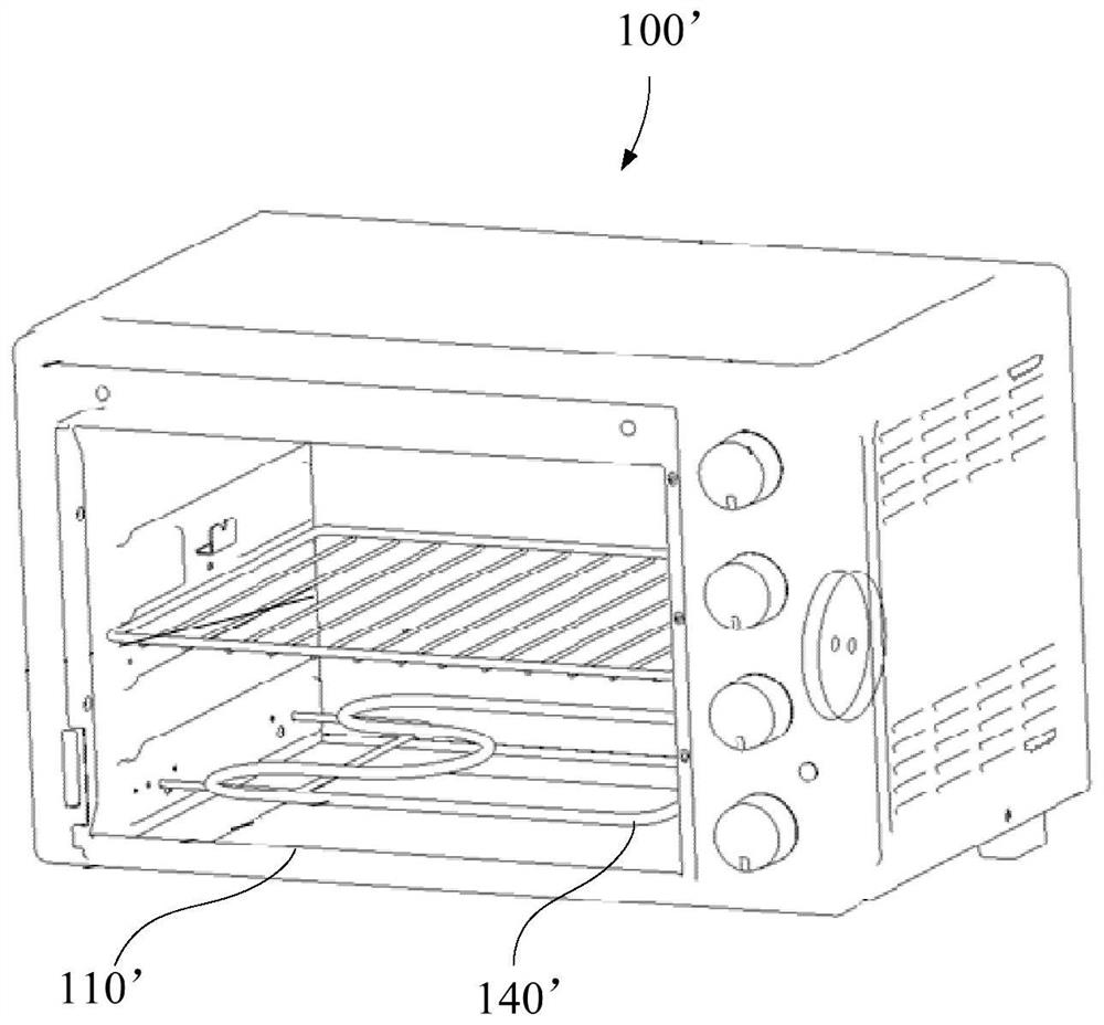
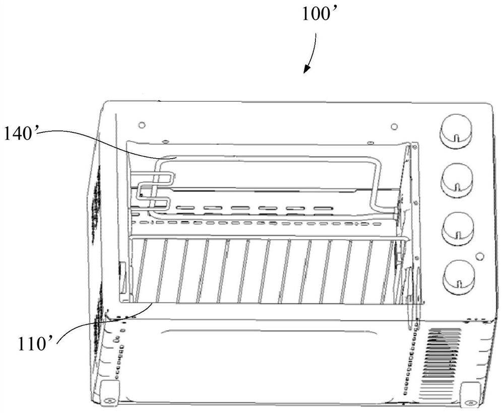
[0064] Specifically, such as image 3 , Figure 4 , Figure 7 , Figure 8 , Figure 9 As shown, the cover plate 120 of the cooking device 100 is arranged on the inside or outside of the cooking cavity 110, and an accommodating cavity 130 is formed between the cover plate 120 and the cooking cavity 110, and the heat source 140 is arranged in the accommodating cavity 130, which can avoid heat source 140 is directly arranged in the cooking cavity 110, during the cooking process, there will be oil stains and food 2...

Embodiment 2

[0068] Such as Figure 3 to Figure 22 As shown, in one embodiment of the present invention, the cooking device 100 is equipped with a cooking cavity 110, a cover plate 120, a heat source 140 and a partition 150, wherein the partition 150 is arranged between the heat source 140 and the cooking cavity 110, and Connect with the cover plate 120.

[0069] In this example, if Figure 4 , Figure 5 , Image 6 , Figure 10 , Figure 11 , Figure 13 , Figure 14 , Figure 15 As shown, a partition 150 is set between the heat source 140 and the cooking cavity 110, and the partition 150 is opposite to a part of the heat source 140. Since the heating value of the heat source 140 itself is not uniform, it is connected to the cover plate 120 through the partition 150 and connected to the part of the heat source 140. Located opposite to the heat source 140, the partition 150 is used to separate the area of ​​the heat source 140 with a high calorific value from the cooking cavity 110, ...

Embodiment 3

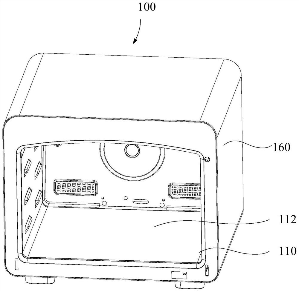
[0073] Such as Figure 3 to Figure 22 As shown, in one embodiment of the present invention, the cooking device 100 includes a cooking cavity 110, a cover plate 120, a heat source 140 and a partition 150, wherein the cooking cavity 110 is configured as a cooking cavity 112 having an opening, and the cooking cavity 110 includes a plurality of cavity walls 114 , and a cover plate 120 is disposed on at least one of the plurality of cavity walls 114 and is located outside the cooking cavity 112 .

[0074] In this example, if Figure 4 , Figure 5 , Image 6 , Figure 7 , Figure 16 , Figure 17 , Figure 18 , Figure 19 As shown, the cooking cavity 110 is configured as a cooking cavity 112 with an opening through which the food 200 to be cooked is placed in or removed from the cooking cavity 110, the cooking cavity 110 includes a plurality of cavity walls 114, The cover plate 120 is arranged on at least one of the plurality of cavity walls 114, so that the accommodating cav...


PUM


Abstract

The invention provides cooking equipment. The cooking equipment comprises a cooking cavity; a cover plate arranged on the cooking cavity, wherein a containing cavity is formed between the cover plate and the cooking cavity; and a heat source arranged in the containing cavity. According to the cooking equipment provided by the invention, the heat source is arranged in the containing cavity, so that the heat source can be prevented from being directly arranged in the cooking cavity, oil stains and food residues can be prevented from being left on the heat source or on the cavity walls of the cooking cavity near the heat source in the cooking process to cause difficult cleaning; meanwhile, the cover plate is arranged on the multiple cavity walls of the cooking cavity or the cover plate covers most of the area of each cavity wall to enlarge the heating area of the cooking cavity, the temperature uniformity in the cooking cavity can be improved, food in the cooking cavity can be heated evenly, the taste and aesthetic feeling of the food are improved, and the good cooking effect is guaranteed.

Description

technical field [0001] The present invention relates to the technical field of kitchen utensils, in particular to cooking equipment. Background technique [0002] As a common cooking equipment in the home kitchen, the oven has functions such as grilling and baking, and can meet the cooking needs of various groups of people. Such as figure 1 with figure 2 As shown, the heat source 140' of the current oven 100' is usually directly built into the upper cavity wall and the lower cavity wall of the cooking cavity 110', so that there will be oil stains and food residues left on the heat source 140' or the heat source 140' during the cooking process. The cavity wall of the nearby cooking cavity 110' is difficult to clean. At the same time, the temperature difference between multiple cavity walls in the cooking cavity 110' is relatively large, and the cooking cavity 110' is heated unevenly, which affects the cooking effect of food. Contents of the invention [0003] The presen...

Claims


Application Information

Patent Timeline
Patent Type & Authority Applications(China)
IPC IPC(8): A47J37/06
CPCA47J37/0629A47J37/0664
Inventor 王文鹏
Owner GUANGDONG MIDEA WHITE HOME APPLIANCE TECH INNOVATION CENT CO LTD
Why Eureka
Try Eureka