A commutation control method for ultrasonic transmission based on excitation phase difference modulation

A control method and a technology for modulating ultrasound, which is applied to conveyors, transportation and packaging, and non-mechanical conveyors. Simple, efficient effect

Active Publication Date: 2022-06-21
HARBIN INST OF TECH
View PDF5 Cites 0 Cited by
  • Summary
  • Abstract
  • Description
  • Claims
  • Application Information

AI Technical Summary

Problems solved by technology

[0004] Publication No. CN111332803A provides the theoretical basis for determining the vibration standing wave and traveling wave components in this type of device, but does not discuss the direction of wave propagation; in summary, the prior art cannot realize pure traveling wave driving or standing wave traveling wave common driven reciprocating motion

Method used


Image

  • A commutation control method for ultrasonic transmission based on excitation phase difference modulation
  • A commutation control method for ultrasonic transmission based on excitation phase difference modulation
  • A commutation control method for ultrasonic transmission based on excitation phase difference modulation

Examples


specific Embodiment approach 1

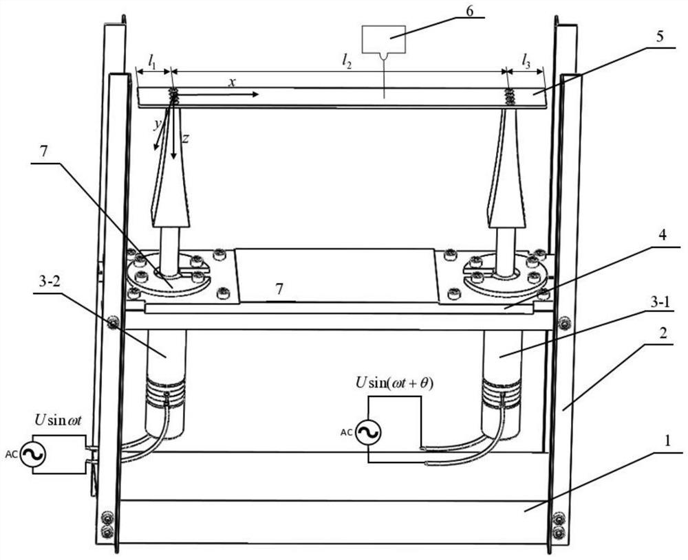
[0089] Combine below Figures 1 to 4 Illustrating this embodiment, a method for controlling the commutation of ultrasonic transmission based on excitation phase difference modulation, the method includes the following steps:

[0090] Step 1: Build an ultrasonic suspension drive device as required, and apply two excitation signals with the same amplitude and frequency to transducer one 3-1 and transducer two 3-2, but with a phase difference θ;

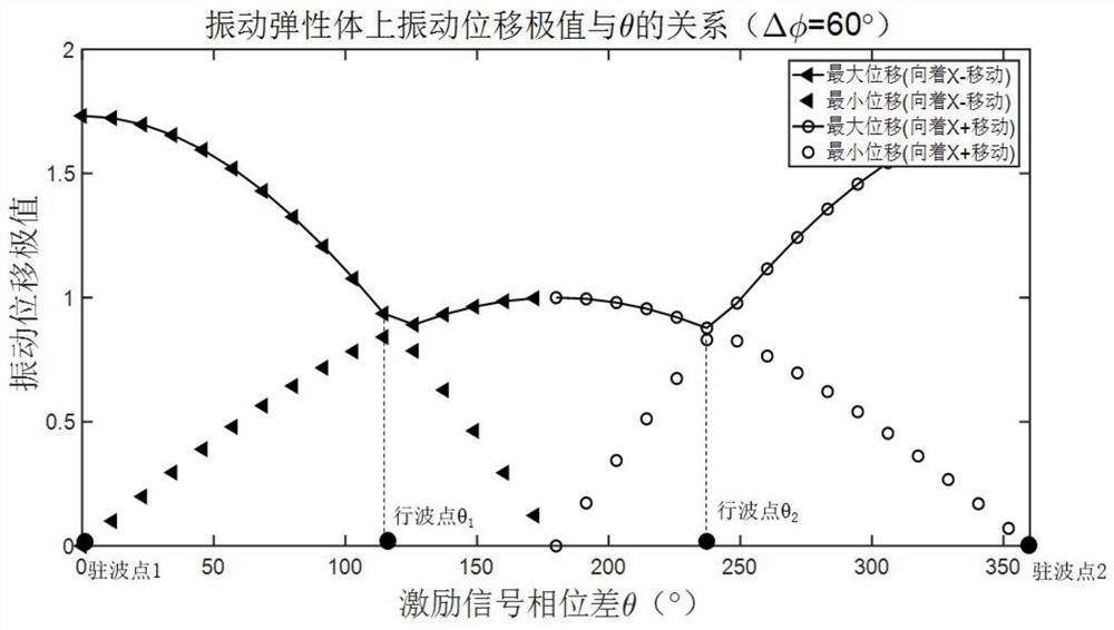
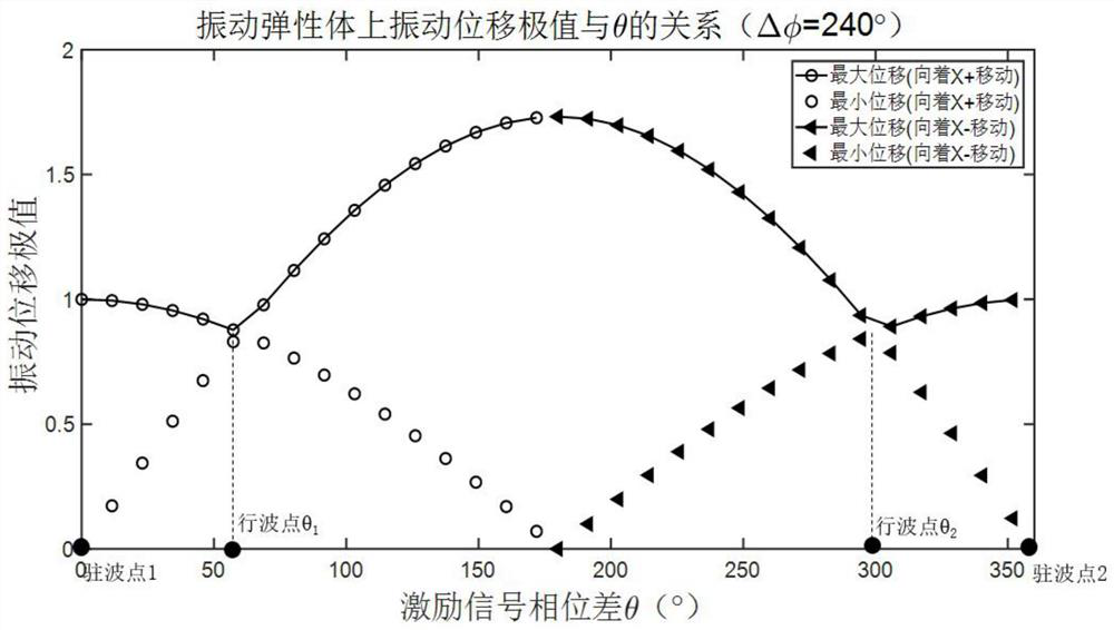
[0091] Step 2: Analyze the vibration displacement of the elastic vibration body 5, and set the equivalent spatial phase difference of the distance between the two support points of the elastic vibration body as Get the maximum amplitude of the elastic vibrating body and minimum amplitude solve get in In the case of constant, the theoretical formula of pure traveling wave θ value is formed; write down the vibration equation f(x, t) of the particle located at x on the elastic vibrating body 5 along the z direction at any time t; ...

specific Embodiment approach 2

[0096] Combine below Figures 1 to 4 This embodiment is described, and the first embodiment is further described in this embodiment. The excitation signal is the mechanical resonance frequency of the ultrasonic suspension drive device operating in the required longitudinal vibration mode; the long-distance ultrasonic suspension transmission is determined in the finite element simulation software. The dynamic model of the device is analyzed by modal simulation analysis, and the mechanical resonance frequency of the two ultrasonic transducers 3-1 and 3-2 in the suspension transmission device working in the longitudinal vibration mode is obtained. The model includes two ultrasonic transducers - 3-1 and 3-2, elastic vibration body 5, and the support structure of the transducer, etc., focusing on the placement of the piezoelectric ceramics of the ultrasonic transducer, the horn and the elastic vibration The structure of body 5 is modeled. The elastic vibrating body 5 is an ultraso...

specific Embodiment approach 3

[0097] Combine below Figures 1 to 4This embodiment will be described. This embodiment will further describe Embodiment 2. The ultrasonic suspension driving device includes a transducer one 3-1, a transducer two 3-2, an elastic vibrating body 5 and a laser vibrometer 6, An elastic vibrating body 5 is detachably and fixedly connected between the vibration output ends of the transducer one 3-1 and the transducer two 3-2, and the laser vibrometer 6 conducts a vibration velocity scanning experiment on the radiation surface of the entire elastic vibrating body 5; Among them, transducer one 3-1 and transducer two 3-2 are installed opposite to each other, and the structural dimensions and electrical parameters of the two transducers are the same, and Langevin piezoelectric ceramic transducers can be used as transducers. Both ends of the elastic vibrating body 5 are respectively fixedly connected to the vibration output ends of the two transducers 1 3-1 and the second transducer 3-2, ...


PUM


Abstract

The present invention relates to the field of ultrasonic standing wave / traveling wave suspension transmission, more specifically, a method for controlling ultrasonic transmission commutation based on excitation phase difference modulation, step 1: applying the same amplitude and frequency to the transducer and the transducer respectively , but there are two excitation signals with a phase difference θ; Step 2: Analyze the vibration displacement of the vibrating elastic body, obtain the maximum and minimum amplitudes of the vibrating elastic body, and obtain the theoretical formula for forming a pure traveling wave θ value under constant conditions Step 3: change the phase difference θ of the two-way excitation signals, and the laser vibrometer performs a vibration scanning experiment on the radiation surface of the entire elastic vibrating body to obtain the phase difference θ of the excitation signals when the amplitudes of each point on the vibrating elastic body are equal, by step 2 Calculate the spatial geometric phase difference corresponding to the current device based on the mathematical relationship between the θ and propagate in different directions.

Description

technical field [0001] The invention relates to the field of ultrasonic standing wave / traveling wave suspension transmission, and more particularly to a commutation control method for ultrasonic transmission based on excitation phase difference modulation. Background technique [0002] The current research on ultrasonic suspension transmission is divided into two types. One is to use ultrasonic standing wave suspension for transmission, which uses standing waves to suspend objects at the sound pressure node; the other is to transmit through near-sound field suspension. However, the speed of standing wave suspension transmission is slow, and the suspension ability of near-sound field suspension transmission is very weak. In order to overcome the shortcomings of these two transmission methods, the current research direction is to apply two excitation signals of the same frequency and amplitude, so that the Traveling waves and standing waves exist at the same time, which increa...

Claims


Application Information

Patent Timeline
Patent Type & Authority Patents(China)
IPC IPC(8): B65G54/00
CPCB65G54/00
Inventor 董惠娟李谋赵杰穆冠宇
Owner HARBIN INST OF TECH
Why Eureka
Try Eureka