
A jigger and a jigging process using the jigger

The technology of a jigger and a pressing mechanism is applied in the field of jigger and jigger, which can solve the problems of reducing the dyeing effect of fabrics, difficult to control the tension force, and large error of the tension force, so as to improve the dyeing effect. , the effect of reducing errors and improving accuracy

Active Publication Date: 2022-07-22
瑞雪蓝色印染科技有限公司
View PDF6 Cites 0 Cited by
  • Summary
  • Abstract
  • Description
  • Claims
  • Application Information

AI Technical Summary

Problems solved by technology

[0004] For the related technologies mentioned above, the inventor thinks that there are the following defects: the jigger first needs to wind the fabric onto the left cloth roll, and then wind the fabric around the cloth guide roll onto the right cloth roll, and then Dyeing the fabric, the dyeing effect of the fabric has a great relationship with the tension of the fabric, and the dyeing effect of the fabric will be improved when the fabric is in a suitable tension during dyeing, but the tension of the fabric on the fabric winding on the left cloth roller The tension is not well controlled, so the tension force and the required tension force during fabric dyeing have a large error, thereby reducing the dyeing effect of the fabric

Method used


Image

  • A jigger and a jigging process using the jigger
  • A jigger and a jigging process using the jigger
  • A jigger and a jigging process using the jigger

Examples


Embodiment Construction

[0051] The present application will be further described in detail below with reference to the accompanying drawings for 1-7.

[0052] The embodiments of the present application disclose a jigger.

[0053] In this embodiment, the model of the force detector 544 is WZN, and the model of the infrared detector 75 is HF-HJ03.

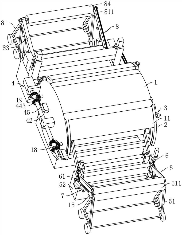
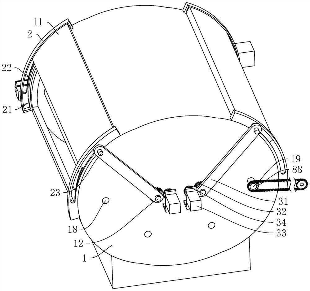
[0054] refer to figure 1 and figure 2 , the jigger includes a cylindrical cylinder 1, the cylinder 1 is equipped with dye liquor, and the inner side wall of the cylinder 1 is rotated and installed with a cloth feeding roller 18 and a cloth discharging roller 19 that are parallel to each other, and the cloth feeding roller 18 and the cloth The rollers 19 are located on the same horizontal plane, while the cloth feeding rollers 18 and the cloth discharging rollers 19 are located above the liquid level of the dye liquor, and a plurality of cloth guide rollers are rotatably installed on the inner wall of the cylinder 1 below the liquid level.

[0055] refer...


PUM


Abstract

The application relates to a jigger and a jigging process using the jigger, and relates to the technical field of fabric processing, including a cylinder block and a cloth inlet. The cloth device includes a first A-frame, a cloth feeding frame, a pressing mechanism and a tensioning mechanism; the first A-shaped frame is arranged on the ground, and the cloth feeding frame is arranged on the ground; the pressing mechanism is arranged on the cloth feeding frame and is set There are two, the tensioning mechanism is set on the cloth feed frame and the fabric is stretched around the tensioning mechanism and used to adjust the tension on the fabric. In the present application, the tensioning force of the fabric is adjusted by a tensioning mechanism, so that the tensioning force of the fabric is the same as the required tensioning force, and then the cloth feeding roller is rotated to wind the fabric on the cloth feeding roller, thus reducing the time of fabric dyeing. The error between the tension force and the required tension force improves the dyeing effect of the fabric.

Description

technical field [0001] The present application relates to the technical field of fabric processing, in particular to a jigger and a jigging process using the jigger. Background technique [0002] During the dyeing process, the jigger is powered by the cloth winding roller. The fabric to be dyed is unwound and released from the left cloth winding roller. On the roll, after the fabric on the left roll cloth roll is finished, it will go back; this reciprocating operation achieves the purpose of dyeing. [0003] In the related art, reference may be made to the Chinese utility model patent with the authorized announcement number CN208201355U, which discloses a new type of jigger. Inside the jigger, there are left cloth winding rollers, right cloth winding rollers and cloth guide rollers. The roller and the right cloth roll are arranged on the upper part of the jigger, and the left and right cloth rolls are in the same horizontal position. There is a dye tank in the lower part of...

Claims


Application Information

Patent Timeline
Patent Type & Authority Patents(China)
IPC IPC(8): D06B3/32D06B23/20D06B23/04
CPCD06B3/32D06B23/20D06B23/04
Inventor 徐志勇佘长富唐孝真
Owner 瑞雪蓝色印染科技有限公司
Learn More