Annular speed-increasing cyclone for vertical well

A cyclone and annulus technology, which is applied in the field of annular speed-increasing cyclones for vertical wells, can solve the problems of reducing drilling timeliness, prolonging the construction period, encountering obstacles and jamming, etc., achieving simple and fast maintenance and realizing environmental protection. The effect of speeding up the air swirl and increasing the radius of rotation

Active Publication Date: 2021-05-07
王树永
View PDF12 Cites 2 Cited by
  • Summary
  • Abstract
  • Description
  • Claims
  • Application Information

AI Technical Summary

Problems solved by technology

When the circulation is stopped, the debris or debris accumulated in the "big belly" well section will start to slide down the wellbore due to gravity. If it slides down to a relatively regular well section and remains or accumulates, it will cause tripping resistance. If it is not handled properly, it may even easily cause a stuck pipe accident; in addition, if the cuttings or pieces fall to the bottom of the well, it will form sand, which will make it impossible to drill to the bottom smoothly, and it needs to be cleared by reaming cycle to prolong the construction period; If cuttings or falling blocks cannot be removed, when they slide down and are carried up by the drilling fluid again to the well section with regular diameter, it is easy to cause poor pump, poor top drive and resistance and stuck phenomenon again.
[0004] Therefore, when there is an irregular well diameter and the formation of "candied haws" or "big belly" wellbore, the drilling fluid will become less effective in carrying cuttings or falling blocks in this well section, which will not only reduce the drilling timeliness, but also prolong the construction period and increase the drilling cost , and bring great hidden dangers to construction safety
[0005] At present, in order to remove accumulated cuttings or falling blocks in this type of well section, the method of adjusting the rheology of the drilling fluid is often used on site, that is, the method of thick slurry or heavy thick slurry. This method mainly increases the viscosity and shear rate of the drilling fluid. However, it is difficult for the cuttings or falling blocks in the edge area far away from the drill tool in the "big belly" due to the flow velocity and flow trajectory. It is started by fluid flushing and then taken away from the area, so the removal efficiency is very low and the effect is poor. It often requires multiple cycles of thick / heavy slurry and multiple short trips for treatment, which increases the cost of drilling fluid and also Extended drilling cycle

Method used


Image

  • Annular speed-increasing cyclone for vertical well
  • Annular speed-increasing cyclone for vertical well
  • Annular speed-increasing cyclone for vertical well

Examples


Embodiment 1

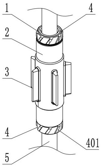
[0036] see Figure 1 to Figure 6 As shown, an annular speed-increasing cyclone for vertical wells includes an inner cylinder 1 , a rubber impeller 3 and an outer cylinder 2 .

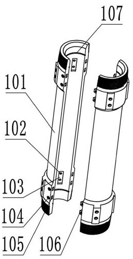
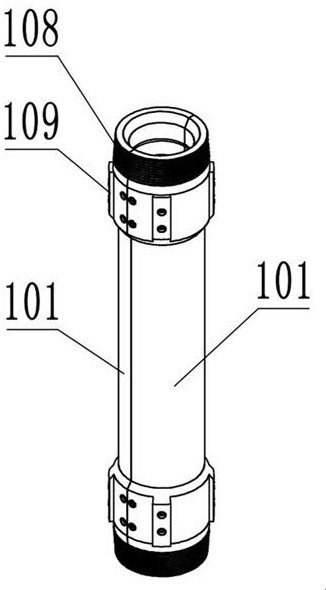
[0037] The inner cylinder 1 is composed of two detachably connected half cylinders 101. The structure of the detachable connection can be that on the opposite end faces of the two half cylinders 101, a group of mutually matching key protrusions 106 and The keyway 105 , the key protrusion 106 and the keyway 105 are correspondingly provided with a pin hole 104 , and a pin is installed in the pin hole 104 .

[0038] In addition, an internal thread can also be provided in the pin hole 104, and the pin is provided with an external thread that matches the pin hole 104. After the pin is matched with the pin hole 104, the assembled inner cylinder 1 is more firm.

[0039] The middle part of the inner cylinder body 1 is waist-shaped and forms a groove for a rubber bucket 301. The upper and lower ends of the inne...

Embodiment 2

[0049] This embodiment is further optimized on the basis of Embodiment 1, specifically:

[0050] The outer wall of the inner cylinder 1 is provided with a positioning protrusion 109, and the inner wall of the outer cylinder is provided with a longitudinal positioning groove 202 adapted to the positioning protrusion 109, wherein there can be two positioning protrusions 109, and they are distributed on the outer wall of the inner cylinder 1. Upper and lower ends.

[0051] Through the cooperation of the positioning protrusion 109 and the positioning groove 202, the stability of the synchronous rotation after the assembly of the outer cylinder 2, the inner cylinder 1, and the rubber impeller 3 is further improved, thereby changing the fluid flow state of the annular space during work and increasing the fluid flow rate , to realize the speed-up of annular swirl.

Embodiment 3

[0053] This embodiment is further optimized on the basis of Embodiment 1, specifically:

[0054] A threaded hole 102 penetrating through the inner cylinder 1 is provided in the jaw groove 103 of the pliers, and a top screw is threaded in the threaded hole 102 .

[0055] By rotating and adjusting the jackscrew, the jaws 110 can be forced to stick more tightly to the drill pipe 5, so that the inner cylinder body 1 and the drill pipe 5 can be fixed more firmly by using the inner tooth surface of the jaws 110 to bite the drill pipe 5 together.


PUM


Abstract

The invention discloses an annular speed-increasing cyclone for a vertical well. The annular speed-increasing cyclone comprises an inner barrel, a rubber impeller and an outer barrel, wherein the inner barrel is formed by splicing two half barrels which are detachably connected; a rubber barrel groove is formed in the middle of the inner barrel; external thread parts are arranged at the upper end and the lower end of the inner barrel; the external thread parts at the two ends are in threaded connection with locking nuts; a group of tong tooth grooves are formed in the inner wall of the inner barrel; matched tong teeth are placed in the tong tooth grooves; the rubber impeller comprises a rubber barrel and a group of blades which are radially connected to the periphery of the rubber barrel; the rubber barrel is sleeved in the rubber barrel groove; the outer barrel is sleeved on the outer side of the inner barrel; the outer barrel and the inner barrel are fixed through the locking nuts; the outer barrel is provided with a group of blade grooves for the blades to extend out; and movable gaps are reserved between the blade grooves and the blades. According to the annular speed-increasing cyclone, transverse shear stress is applied to drilling fluid at an underground annular position by utilizing the rotation of the rubber impeller, and the flow velocity of the drilling fluid is increased, so that an effect of clearing rock debris falling blocks accumulated and retained in a borehole is achieved.

Description

technical field [0001] The invention relates to the technical field of petroleum equipment, in particular to an annular speed-increasing cyclone for vertical wells. Background technique [0002] In the process of oil drilling construction, the well wall is often unstable and collapsed due to various reasons, thereby forming an irregular well diameter. "Candied haws" or "big belly" wells. [0003] In this type of irregular well diameter section, due to the significant decrease in the return velocity of the annular space and the change of the flow trajectory of the drilling fluid fluid area, the ability of the drilling fluid to carry cuttings or rock fragments is also greatly reduced, and some cuttings or rocks The falling blocks perform repeated rising and falling movements in the "big belly" well section, and gradually accumulate and remain away from the drilling tool and the high flow rate area. When the circulation is stopped, the debris or debris accumulated in the "big...

Claims


Application Information

Patent Timeline
Patent Type & Authority Applications(China)
IPC IPC(8): E21B21/00E21B21/08
CPCE21B21/00E21B21/08
Inventor 王树永李文明张高峰
Owner 王树永
Why Eureka
Try Eureka