Miniature gas turbine with bearing embedded in motor

A micro gas turbine and gas turbine technology, which is applied in gas turbine installations, electrical components, machines/engines, etc., can solve problems such as vibration, unstable operation of rotor system, and limitation of the size of the rear of the rotating shaft.

Pending Publication Date: 2021-05-07
刘慕华
View PDF0 Cites 1 Cited by
  • Summary
  • Abstract
  • Description
  • Claims
  • Application Information

AI Technical Summary

Problems solved by technology

The invention can solve the size limitation of the tail of the rotating shaft and

Method used


Image

  • Miniature gas turbine with bearing embedded in motor
  • Miniature gas turbine with bearing embedded in motor
  • Miniature gas turbine with bearing embedded in motor

Examples


Embodiment 1

[0035] Embodiment 1 Motor embedded bearing type micro gas turbine

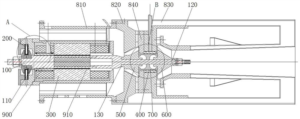
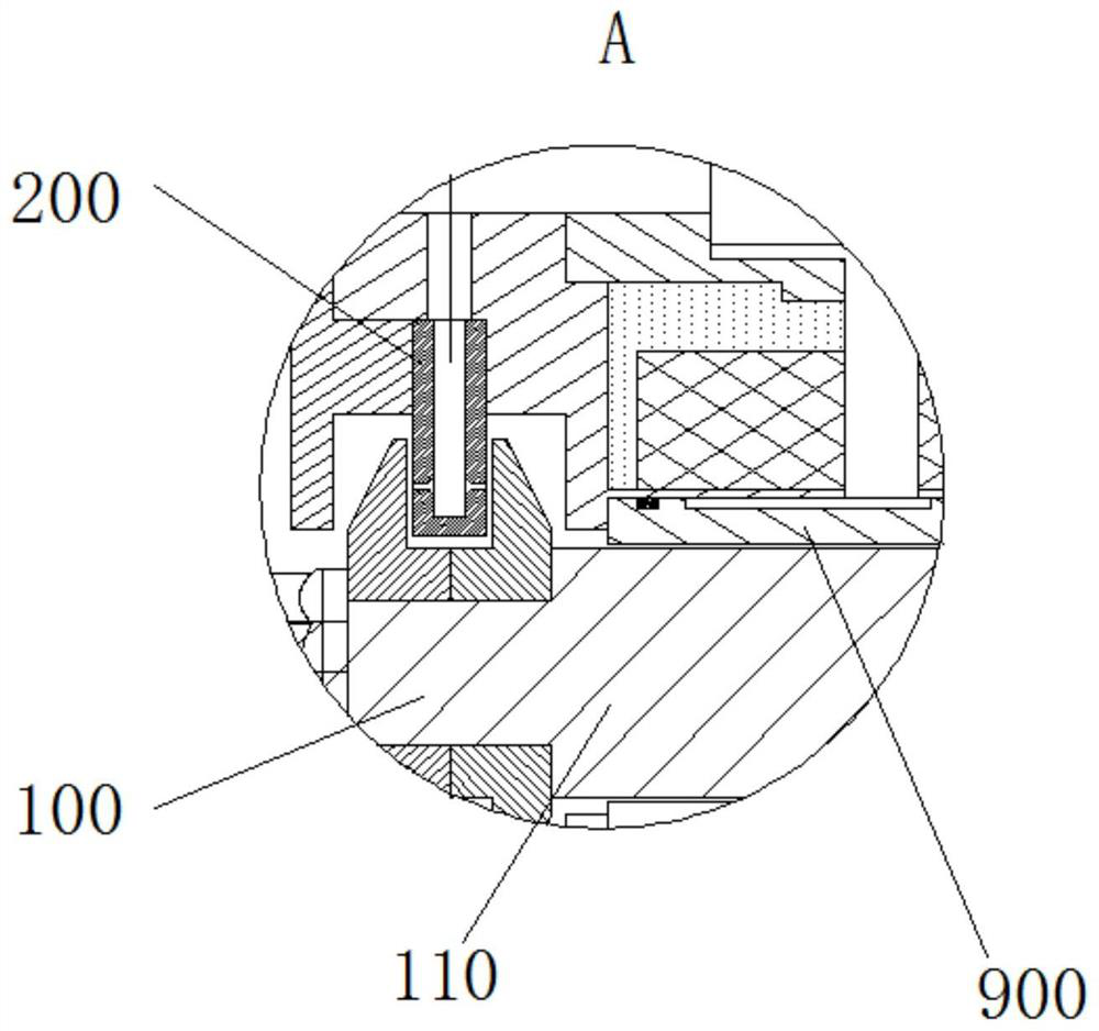
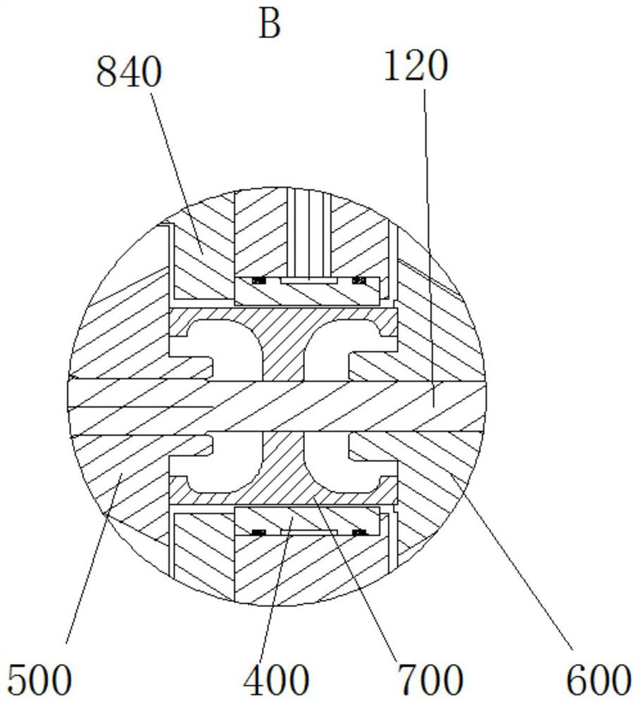
[0036] A bearing-embedded micro gas turbine with a motor, including a rotor system, a motor case 810, a gas turbine case 820 and a combustion chamber 830, such as figure 1 , figure 2 , image 3 shown.

[0037] The rotor system includes a rotating shaft 100. The rotating shaft 100 includes an integrally formed first shaft segment 110 and a second shaft segment 120. The diameter of the first shaft segment 110 is larger than the diameter of the second shaft segment 120. The first shaft segment 110 and the second shaft segment A step surface 130 is formed at the transition of 120; the thrust bearing 200, the first radial bearing 900 and the motor 300 are arranged in sequence on the first shaft section 110; the compressor 500 and the second radial bearing 400 are arranged in sequence on the second shaft section 120 and the turbine 600; one end of the compressor 500 abuts against the stepped surface 130; a third...

Embodiment 2

[0049] Embodiment 2 Motor built-in bearing type micro gas turbine

[0050] Same as Embodiment 1, the difference from Embodiment 1 is that: the cooperation relationship between the third bearing 910 and the motor 300 is as follows:

[0051] Such as Figure 5 As shown, the third bearing 910 is shrink-fitted in the motor 300 and tightly fitted with the motor 300. A part (such as a pin) to prevent circumferential rotation is provided between the motor 300 and the third bearing 910. One end is fixed in the motor 300, and the other end is fixed on the outer wall of the third bearing 910; there is a predetermined gap between the third bearing 910 and the rotating shaft 100, and the rotating shaft 100 is supported in the third bearing 910 by the air film in the predetermined gap; , the third bearing 910 is used as a radial bearing.

Embodiment 3

[0052] Embodiment 3 Motor built-in bearing type micro gas turbine

[0053] Same as Embodiment 2, the difference from Embodiment 2 is that the cooperation relationship between the third bearing 910 and the motor 300 is as follows:

[0054] exist Figure 5 On the basis of the matching relationship shown, a damper 911 is provided on the surface of the third bearing 910. The specific method is: at least one ring of rubber coating is provided around the outer wall of the third bearing 910, such as Image 6 , Figure 7 shown.


PUM


Abstract

The invention discloses a miniature gas turbine with a bearing embedded in a motor. The miniature gas turbine comprises a rotor system, a motor casing, a gas turbine casing and a combustion chamber, wherein the rotor system comprises a rotating shaft, a thrust bearing, a first radial bearing, the motor, a gas compressor, a second radial bearing and a turbine are sequentially arranged on the rotating shaft, and a third bearing is arranged between the rotating shaft and the motor; the motor casing covers the periphery of the motor; the gas turbine casing covers the peripheries of the gas compressor and the turbine and is connected with the motor casing; and the combustion chamber is connected with the gas turbine casing. According to the miniature gas turbine with the bearing embedded in the motor, the rotating shaft is supported by the bearings at the two ends, stress is uniform, the situation that the weight is unbalanced due to suspension of the shaft end of a rotor can be avoided, operation stability is good, and the adjustable range of the size of the rotating shaft in the axial direction is large. The radial bearing is arranged in the motor, so that mutual disturbance between the motor and the rotating shaft during high-speed rotation is reduced, and the stability of the rotor during operation of the gas turbine is effectively enhanced.

Description

technical field [0001] The invention relates to a motor-embedded bearing type micro-gas turbine, which belongs to the technical field of micro-gas turbines. Background technique [0002] In the technical field of micro gas turbine power generation, a micro gas turbine generating set usually includes a coaxially installed generator and a micro gas turbine. Specifically, a micro gas turbine mainly includes three major components: a compressor, a combustion chamber, and a turbine. After entering the compressor, the air is compressed into high-temperature and high-pressure air, and then supplied to the combustion chamber for mixed combustion with fuel. The high-temperature and high-pressure gas produced by it is in the turbine The medium expansion does work, drives the turbine to rotate, and then drives the generator to generate electricity. Because the magnetic components and coil windings in the generator are not resistant to high temperature, the generator cannot be installe...

Claims


Application Information

Patent Timeline
IPC IPC(8): F02C6/00F02C7/32F02C7/06F02C7/04H02K5/167F04D29/053
CPCF02C6/00F02C7/32F02C7/06F02C7/04H02K5/1672F04D29/053Y02T50/60
Inventor 靳普
Owner 刘慕华
Why Eureka
Try Eureka