
Soil cutter for preparing specific angle for remolded soil

A technology for reshaping soil from a specific angle, applied in the field of laboratory preparation and reshaping soil, which can solve problems such as mass loss and moisture content change

Pending Publication Date: 2021-05-07
XI'AN UNIVERSITY OF ARCHITECTURE AND TECHNOLOGY
View PDF0 Cites 1 Cited by
  • Summary
  • Abstract
  • Description
  • Claims
  • Application Information

AI Technical Summary

Problems solved by technology

[0003] At present, the laboratory generally prepares two soil samples for the preparation of angled remolded soil, and then cuts the soil samples at a specific angle through a mold, and then sticks them together for testing, which will cause mass loss and moisture content in the process change

Method used


Image

  • Soil cutter for preparing specific angle for remolded soil
  • Soil cutter for preparing specific angle for remolded soil
  • Soil cutter for preparing specific angle for remolded soil

Examples


Embodiment 1

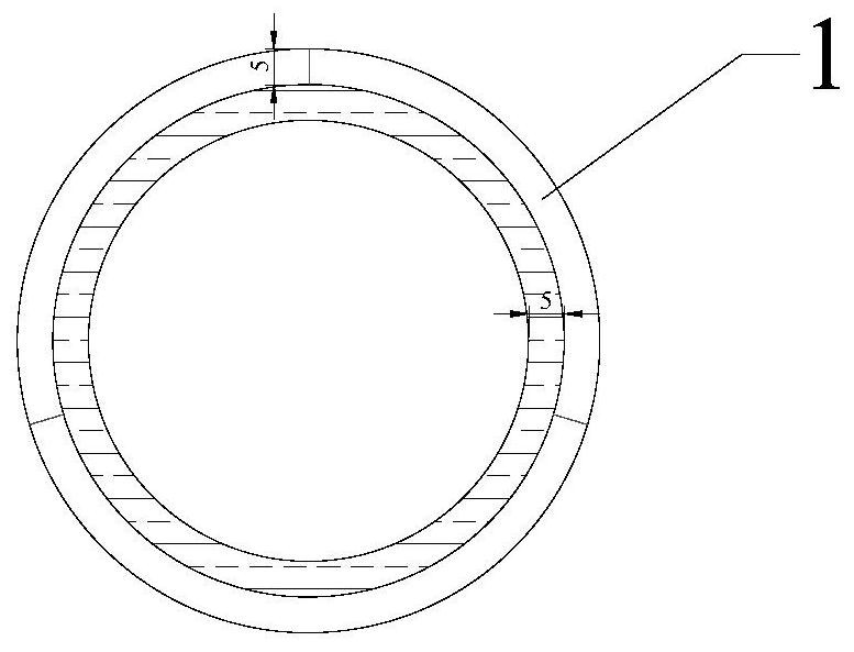
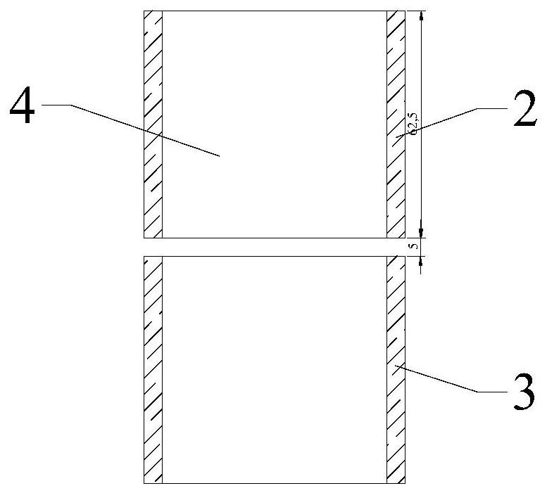
[0053] refer to figure 1 , Figure 4 , Figure 14 and Figure 15, the cutting angle of the present embodiment is 30 °, and the specific operation process is: 1) according to the original equipment of the laboratory, install the upper mold and the lower mold, and then place the outer ring 1, so that the outer ring 1 just embeds the upper mold and the lower mold 2) Put the soil sample 4 on the wooden board 29, and fix the guard plate 20 on the board 29 by screws 28. On the wooden board 29, move the rotating shaft 22 to the position where the scale line 18 on the first horizontal groove and the second horizontal groove is 30 degrees, turn the hand wheel 17 to reach the 30 degree of the dial 16, tighten the first nut 25, and fix the whole device 3) Put the steel wire 34 into the first vertical groove and the second vertical groove, screw on the upper cover 24, and cut the soil sample 4 through the steel wire 34.

Embodiment 2

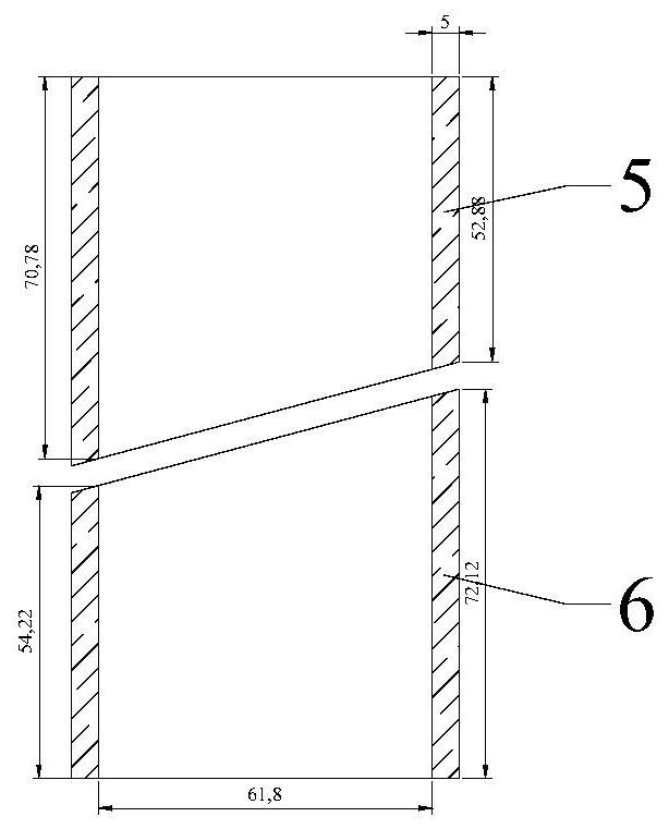
[0055] refer to figure 1 , Figure 6 , Figure 14 and Figure 16 , the cutting angle of the present embodiment is 60 °, and the specific process is: 1) according to the original equipment of the laboratory, install the upper mold and the lower mold, and then place the outer ring 1, so that the outer ring 1 just embeds in the upper mold and the lower mold 2) Put the soil sample 4 on the plank 29, and fix the guard plate 20 on the plank by screws 28 On 29, move the rotating shaft 22 to the position where the scale line 18 on the first horizontal groove and the second horizontal groove is 60 degrees, turn the hand wheel 17 to reach 60 degrees of the dial 16, tighten the first nut 25 before and after, and fix the whole device 3) Put the steel wire 34 into the first vertical groove and the second vertical groove, screw on the upper cover 24, and cut the soil sample 4 through the steel wire 34.

Embodiment 3

[0057] refer to Figure 7 , Figure 8 and Figure 14 , the cutting angle of the present embodiment is 90 °, and the specific process is: 1) according to the original equipment of the laboratory, the upper mold and the lower mold are installed, and then the outer sleeve ring 1 is placed, wherein the outer sleeve ring 1 just embeds the upper mold and the lower mold The gap between the inner collar and the outer collar 1 forms a whole, brush paraffin, remove the outer collar 1 after making the soil sample 4; 2) put the soil sample 4 on the plank 29, and fix the guard plate 20 by screws 28 On the wooden board 29, move the rotating shaft 22 to the position where the scale line 18 on the first horizontal groove and the second horizontal groove is 90 degrees, turn the hand wheel 17 to reach the 90 degree of the dial 16, tighten the front and rear first nuts 25, and fix it The whole device; 3) put the steel wire 34 into the first vertical groove and the second vertical groove, screw...


PUM


Abstract

The invention discloses a soil cutter for preparing a specific angle for remolded soil. A soil sample fixing device comprises a wood plate and a rotating shaft; a first horizontal groove and a first vertical groove are formed in one side face of the box body, and a second horizontal groove and a second vertical groove are formed in the other side face of the box body. The wood plate is located in the box body and is of a cuboid structure, a hand wheel is fixed to one end of the rotating shaft, the other end of the rotating shaft penetrates through the first horizontal groove, the wood plate and the second horizontal groove, a plurality of rubber strips are arranged on the surface of the wood plate, two protection plates are arranged on the wood plate, a soil sample is located on the wood plate, and the soil sample is located between the two protection plates; the wire saw device comprises a steel wire, an annular reinforcing steel bar and a U-shaped handle, the two ends of the steel wire are fixed to the annular reinforcing steel bar, the middle of the steel wire penetrates through the first vertical groove and the second vertical groove, the middle of the steel wire makes contact with the soil sample, the soil cutter can cut the soil sample into a specific angle, and the quality and the water content cannot be changed.

Description

technical field [0001] The invention belongs to the technical field of preparing remolding soil in a laboratory, and relates to a soil cutter for preparing specific angles for remolding soil. Background technique [0002] In geotechnical engineering laboratories, experiments on remolded soil samples are often carried out, and most of the current patents are for the treatment of undisturbed soil. [0003] At present, the laboratory generally prepares two soil samples for the preparation of angled remolded soil, and then cuts the soil samples at a specific angle through a mold, and then sticks them together for testing, which will cause mass loss and moisture content in the process changes and other changes. Contents of the invention [0004] The purpose of the present invention is to overcome the above-mentioned shortcoming of prior art, provide a kind of soil cutter that prepares specific angle to remodeling soil, this soil cutter can cut soil sample into specific angle, ...

Claims


Application Information

Patent Timeline
IPC IPC(8): G01N1/28
CPCG01N1/28G01N1/286G01N2001/2873
Inventor 许健孙菲周立阳杨少飞赵向科谭龙贞王瑞涛李涛
Owner XI'AN UNIVERSITY OF ARCHITECTURE AND TECHNOLOGY
Learn More