
Linear coil inductor formed by continuously winding flat wire of electronic component

A technology of electronic components and coil inductance, applied in the direction of transformer/inductor cooling, electrical components, electrical component structure association, etc., can solve problems such as explosion, component damage, and internal temperature cannot be dissipated in time

Inactive Publication Date: 2021-05-07
深圳爱仕特科技有限公司
View PDF1 Cites 0 Cited by
  • Summary
  • Abstract
  • Description
  • Claims
  • Application Information

AI Technical Summary

Problems solved by technology

[0003] With the continuous improvement of inductors, the application of linear coil inductors wound with flat wires has gradually become popular. However, under long-term working conditions, the internal temperature cannot be dissipated in time, and the temperature of the working environment continues to accumulate. , leading to component damage, or even explosion, it is necessary to design a linear coil inductor with flat wires for electronic components to solve the above problems

Method used


Image

  • Linear coil inductor formed by continuously winding flat wire of electronic component
  • Linear coil inductor formed by continuously winding flat wire of electronic component
  • Linear coil inductor formed by continuously winding flat wire of electronic component

Examples


Embodiment 1

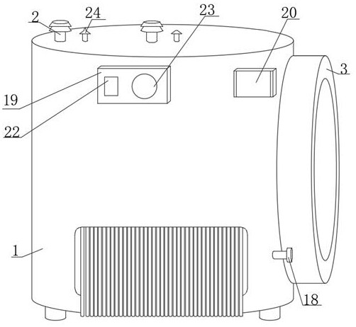
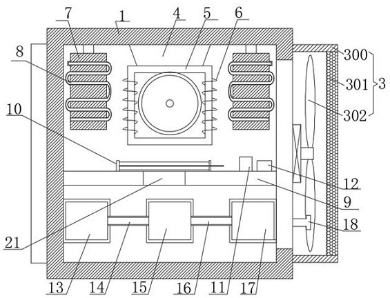
[0025] Embodiment one, such as figure 1 and 2 As shown, the present invention provides a technical solution: a linear coil inductor wound with flat wires of electronic components, including an inductor body 1, and the top of the inductor body 1 is fixedly installed with a first external terminal 2 and a terminal 24. The right side of the inductor body 1 is fixedly installed with a heat dissipation mechanism 3, the inner wall of the top of the inductor body 1 is fixedly installed with a second external terminal 4, and the bottom end of the second external terminal 4 is fixedly connected with a magnetic core 5, and the magnetic core The surface of 5 is wound with a winding wire group 6, the inner wall of the top of the inductor body 1 is fixedly connected with a heat sink 7, and the front of the heat sink 7 is fixedly connected with a condenser 8, and the inner wall of the inductor body 1 is provided with a plate 9, And the top of the board 9 is fixedly installed with a fuse 10...

Embodiment 2

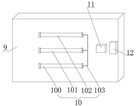
[0029] Embodiment two differs from embodiment one in that: as Figure 1-4 , the present invention provides a technical solution: a linear coil inductor wound with a flat wire of an electronic component, comprising an inductor body 1, a first external terminal 2 and a terminal 24 are fixedly installed on the top of the inductor body 1, The right side of the inductor body 1 is fixedly installed with a heat dissipation mechanism 3, the inner wall of the top of the inductor body 1 is fixedly installed with a second external terminal 4, and the bottom end of the second external terminal 4 is fixedly connected with a magnetic core 5, and the magnetic core 5 The surface is wound with a winding wire group 6, the inner wall of the top of the inductor body 1 is fixedly connected with a heat sink 7, and the front of the heat sink 7 is fixedly connected with a condenser 8, and the inner wall of the inductor body 1 is provided with a plate 9, and is A fuse 10, a voltage detector 11 and a c...


PUM


Abstract

The invention discloses a linear coil inductor formed by continuously winding a flat wires of an electronic component. The linear coil inductor comprises an inductor body, the top of the inductor body is fixedly provided with a first external connection end and a wiring end, the right side of the inductor body is fixedly provided with a heat dissipation mechanism, the inner wall of the top of the inductor body is fixedly provided with a second external connection end, the bottom end of the second external connection end is fixedly connected with a magnetic core, a winding wire set is wound on the surface of the magnetic core, and cooling fins are fixedly connected to the inner wall of the top of the inductor body. According to the linear coil inductor wound by the flat wire, the inductor body can generate a large amount of heat in the long-time use process, at the moment, an internal coil is short-circuited, a fuse wire is fused, a circuit, a magnetic latching switch and a voltage detector are cut off, when the internal voltage is too high, the magnetic latching switch is switched off, the operation of the inductor body is stopped, the explosion-proof effect is achieved, dual protection is achieved, and the reliability is enhanced.

Description

technical field [0001] The invention relates to the technical field of inductors for electronic components, in particular to a linear coil inductor wound with flat wires for electronic components. Background technique [0002] Inductors are components that can convert electrical energy into magnetic energy and store it. Inductors are similar in construction to transformers, but with only one winding. Inductors have a certain inductance, which only resists changes in current. If the inductor is in a state where no current is flowing, it will try to block the current from flowing through it when the circuit is on; if the inductor is in a state where current is passing, it will try to maintain the current when the circuit is off. [0003] With the continuous improvement of inductors, the application of linear coil inductors wound with flat wires has gradually become popular. However, under long-term working conditions, the internal temperature cannot be dissipated in time, an...

Claims


Application Information

Patent Timeline
IPC IPC(8): H01F27/08H01F27/22H01F27/40
CPCH01F27/085H01F27/22H01F27/402
Inventor 陈宇朱超群姚金才
Owner 深圳爱仕特科技有限公司
Learn More