
Clock fault detector

A fault detection and detector technology, applied in instruments, measuring devices, measuring devices, etc., can solve the problems of inconvenient handling of errors, sensitive to process changes in response time, and overall performance deterioration, and achieve the effect of optimizing performance and high precision.

Active Publication Date: 2021-05-07
ARTERY TECH CO LTD
View PDF9 Cites 0 Cited by
  • Summary
  • Abstract
  • Description
  • Claims
  • Application Information

AI Technical Summary

Problems solved by technology

Conventional clock failure detectors have certain problems. In particular, their response time (e.g., the delay time of a pulse representing a clock failure relative to the point in time at which the clock failure occurs) is typically constant and independent of the input clock period, which can be Inconvenience for incorrect disposal of electronic devices
For example, the above response time cannot be shortened as the input clock becomes faster
As another example, the above response time cannot be increased as the input clock becomes slower
In addition, the aforementioned response times are typically sensitive to process variations, which can cause inaccuracies in the operation of electronic devices, degrading overall performance

Method used


Image

  • Clock fault detector
  • Clock fault detector
  • Clock fault detector

Examples


Embodiment Construction

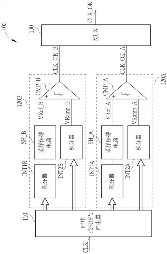
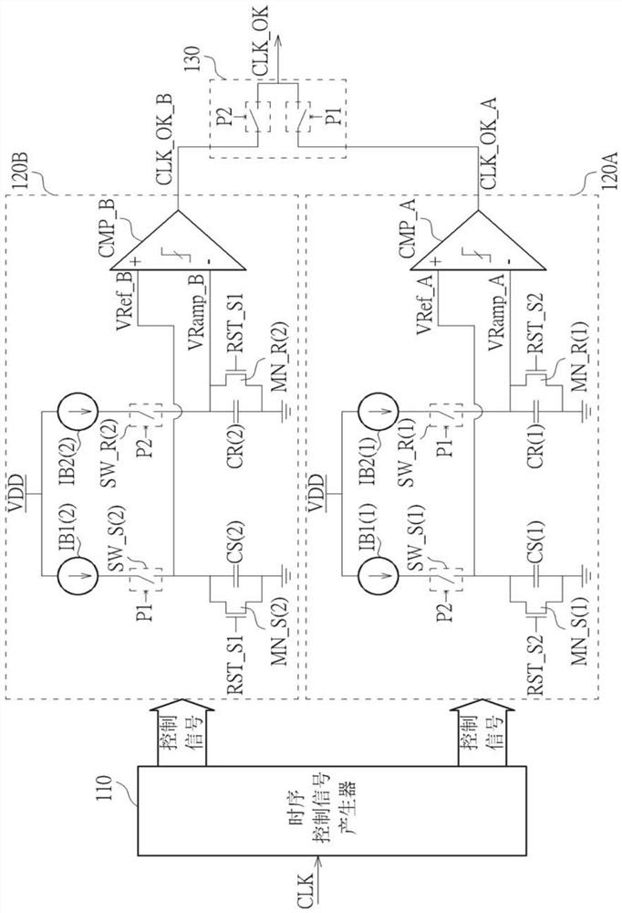
[0048] figure 1 It is a schematic diagram of a clock failure detector 100 according to an embodiment of the present invention. The clock failure detector 100 may include a timing control signal generator 110, and at least one clock failure detection module coupled to the timing control signal generator 110, such as clock failure detection modules 120A and 120B. The timing control signal generator 110 can be used to receive a clock signal CLK, and generate a plurality of control signals according to the clock signal CLK for timing control of the clock failure detector 100, and the at least one clock failure detection module such as a clock failure detection module 120A and 120B can be used for clock failure detection according to the plurality of control signals. In particular, the aforementioned at least one clock failure detection module such as the clock failure detection modules 120A and 120B may include a plurality of first integrators and a plurality of sample-and-hold c...


PUM


Abstract

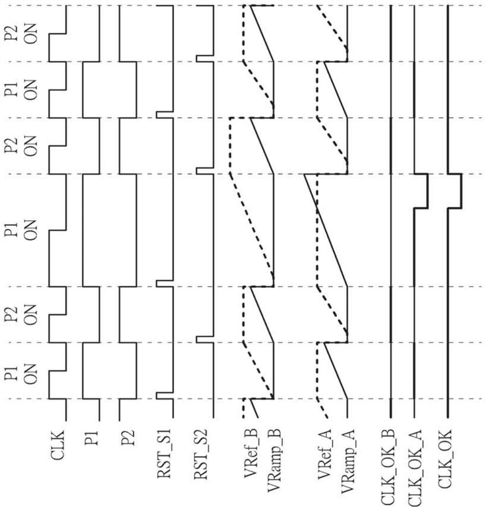
The invention discloses a clock fault detector, and the detector comprises a time sequence control signal generator and a clock fault detection module which can respectively generate a control signal according to a clock signal and perform clock fault detection according to the control signal respectively. The clock fault detection module may include a first integrator, a sample hold circuit, a second integrator, and a comparator. The first integrator can convert previous clock periods of the clock signals into reference voltages according to ping-pong mode control signals in the control signals. The sampling and holding circuit can sample and hold the reference voltage according to the ping-pong mode control signal; the second integrator can convert the current clock period of the clock signal into a ramp signal; and the comparator can compare the ramp signal with at least one reference voltage to generate a comparison result signal for indicating whether the clock signal is normal or not. Compared with a traditional architecture, the clock fault detector has higher precision in process, and can enable the electronic device to achieve optimized efficiency.

Description

technical field [0001] The present invention relates to electronic circuits, in particular to a clock fail detector. Background technique [0002] Clock failure detectors are important fundamental circuits in electronic devices. Conventional clock failure detectors have certain problems. In particular, their response time (e.g., the delay time of a pulse representing a clock failure relative to the point in time at which the clock failure occurs) is typically constant and independent of the input clock period, which can be Inconvenience for mishandling of electronic devices. For example, the above response time cannot be shortened as the input clock becomes faster. As another example, the above response time cannot be increased as the input clock becomes slower. Furthermore, the aforementioned response times are typically sensitive to process variations, which can cause inaccuracies in the operation of electronic devices, degrading overall performance. Therefore, a novel...

Claims


Application Information

Patent Timeline
Patent Type & Authority Applications(China)
IPC IPC(8): H03K5/125
CPCH03K5/125H03K5/24G11C27/02G06F1/06G01R31/31727G01R19/16528G06F1/14
Inventor 郝报田王维铁李超
Owner ARTERY TECH CO LTD
Learn More