Dustproof crushing device for construction waste recycling

A construction waste and crushing device technology, applied in the field of construction, can solve the problems of affecting the working environment, easily generating a lot of dust, and the crushing effect of construction waste is not ideal.

Active Publication Date: 2021-05-11
ANHUI XINLU CONSTR ENG GRP
View PDF11 Cites 1 Cited by
  • Summary
  • Abstract
  • Description
  • Claims
  • Application Information

AI Technical Summary

Problems solved by technology

[0003] During the recycling process of construction waste, in order to improve the utilization rate of the follow-up space and carry out the recycling operation, it needs to be crushed; the traditional construction waste crushing device generally has a relatively si...

Method used


Image

  • Dustproof crushing device for construction waste recycling
  • Dustproof crushing device for construction waste recycling
  • Dustproof crushing device for construction waste recycling

Examples


Embodiment 1

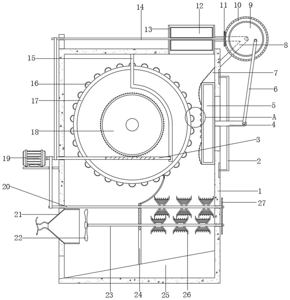
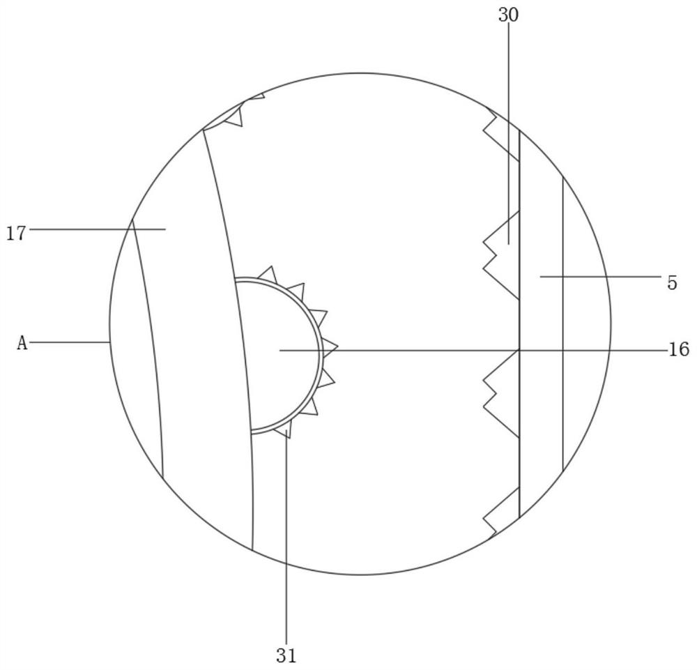
[0030] refer to Figure 1-5 , a dust-proof crushing device for recycling construction waste, comprising a casing 1, a feeding hopper 13 is welded on the top of the casing 1, a shaft column is rotatably connected to the end of the casing 1 near the top through a bearing, and the outer wall of the shaft column is connected by a key There is a roller 17, the outer wall of the roller 17 is welded with convex strips 16 distributed at equal distances, and the side of the casing 1 close to the roller 17 is provided with a pressing mechanism, and the pressing mechanism includes a side of the casing 1. The end arm 4 is slidably connected to the inner wall of the sliding groove, and a cube-shaped rubbing block 5 is welded on one side of the end arm 4, and the rubbing block 5 is welded with equidistantly distributed rubbing blocks 5 on the side close to the roller 17. The kneading concave teeth 30 have a trapezoidal structure as a whole, the top outer wall of the rubbing block 5 is welde...

Embodiment 2

[0041] refer to figure 1 and Image 6 , a dust-proof crushing device for recycling construction waste. Compared with Embodiment 1, this embodiment also includes an arc end block 34 welded to both ends of one side of the rubbing block 5, and the arc end block 34 and the material guide top block 7 The outer walls of each are welded with diamond-shaped blocks 35 distributed equidistantly; some waste materials can be in contact with the top block 7 of the guide material during the input process, and the diamond-shaped blocks 35 are used to realize pre-crushing treatment, and the arc-end blocks 34 and the diamond-shaped blocks on their surfaces Block 35 can cooperate with the reciprocating operation of rubbing block 5 itself up and down, improving the extrusion effect with roller 17.

[0042] When the present invention is in use: the set arc end block 34 and the rhombus block 35 on the arc end block 34 and the top block 7 of the guide material, part of the waste material can conta...


PUM


Abstract

The invention belongs to the technical field of construction, particularly relates to a dustproof crushing device for construction waste recycling, and aims to solve the problems that a conventional construction waste crushing device is relatively simple in structure, relatively simple in crushing mechanism design and general in crushing effect. The following scheme is provided: the dustproof crushing device comprises a shell, a feeding hopper is welded at the top end of the shell, the end, close to the top, of the shell is rotationally connected with a shaft column through a bearing, the outer wall of the shaft column is in key connection with a grinding roller, convex strips distributed at equal intervals are welded to the circumferential outer wall of the grinding roller, a counter-pressing mechanism is arranged on the side, close to the grinding roller, of the shell and comprises a sliding groove formed in one side of the shell, the inner wall of the sliding groove is slidably connected with an end arm, and a cubic rubbing block is welded to one side of the end arm. In the running process of a driving motor, the grinding roller can be driven to rotate under the transmission action of a worm and a worm gear, and waste is effectively extruded and ground in cooperation with the rubbing block.

Description

technical field [0001] The invention relates to the technical field of construction, in particular to a dust-proof crushing device for recycling construction waste. Background technique [0002] Construction waste refers to the muck, spoil, waste material, silt and other wastes generated during the construction, laying, demolition and repair of various buildings, structures, and pipe networks by construction units or individuals. According to the source classification, construction waste can be divided into engineering muck, decoration waste, demolition waste, engineering mud and so on. These materials are of no help to the building itself, but they are substances produced during the construction process and need to be dealt with accordingly, so as to achieve the ideal project construction. It is precisely because it is a whole process, so The consideration of its links is more important. With the acceleration of industrialization and urbanization, the construction industr...

Claims


Application Information

Patent Timeline
IPC IPC(8): B02C4/12B02C4/28B02C4/30B02C4/34B02C4/40B02C4/42B02C19/20B02C23/02
CPCB02C4/12B02C4/28B02C4/286B02C4/30B02C4/34B02C4/40B02C4/42B02C19/20B02C2201/02B02C2201/06
Inventor 魏毅
Owner ANHUI XINLU CONSTR ENG GRP
Why Eureka
Try Eureka