
Cutting fluid treatment device for industrial processing machine tool

A technology for processing machine tools and processing devices, which is applied to metal processing machinery parts, metal processing equipment, manufacturing tools, etc., and can solve problems such as increased production costs, damage to parts, waste of resources, etc.

Active Publication Date: 2021-05-11
CHANGZHOU INST OF MECHATRONIC TECH
View PDF8 Cites 0 Cited by
  • Summary
  • Abstract
  • Description
  • Claims
  • Application Information

AI Technical Summary

Problems solved by technology

[0003] However, the existing cutting fluid is easy to be mixed with a large amount of metal waste after use, so that the cutting fluid cannot be recycled, which not only causes waste of resources, but also increases production costs.
Most of the existing metal cutting fluid recovery devices filter metal impurities such as metal fragments mixed in the cutting fluid and then store them or use them in other fields. Since the cutting fluid contains some small metal particles, it is easy to Damage to parts, cooling of parts that can no longer be precision processed is wasteful and increases production costs

Method used


Image

  • Cutting fluid treatment device for industrial processing machine tool
  • Cutting fluid treatment device for industrial processing machine tool
  • Cutting fluid treatment device for industrial processing machine tool

Examples


Embodiment Construction

[0026] The technical solutions in the embodiments of the present invention will be clearly and completely described below in conjunction with the drawings in the embodiments of the present invention.

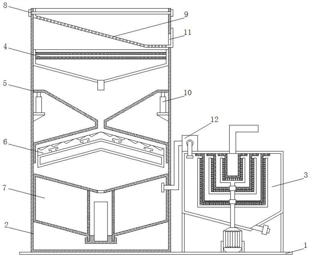
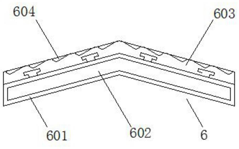
[0027] see Figure 1-6 Description of this embodiment, a cutting fluid processing device for industrial processing machine tools, which includes a bottom plate 1, an outer box 2, an overflow mechanism 3, a filter mechanism 4, a deflector 5, an adsorption mechanism 6, and a sedimentation adsorption mechanism 7. The bottom plate 1 is fixedly connected with the outer box 2 and the overflow mechanism 3, and the inside of the outer box 2 is fixedly connected with a filter mechanism 4, a deflector 5, an adsorption mechanism 6 and a sedimentation adsorption mechanism 7 in sequence from top to bottom;

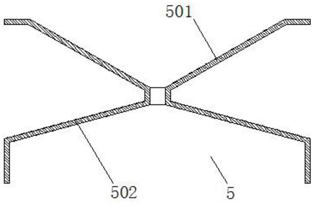
[0028] The deflector 5 includes an upper deflector 501 and a lower deflector trough 502, the two ends of the upper deflector 501 are fixedly connected with the inner wall of the outer bo...


PUM


Abstract

The invention provides a cutting fluid treatment device for an industrial processing machine tool, and belongs to the technical field of processing machine tools. The problems that an existing cutting fluid for the machine tool cannot be reused, waste is caused, and the production cost is increased are solved. The device comprises a bottom plate, an outer box, an overflow mechanism, a filtering mechanism, a fluid director, an adsorption mechanism and a precipitation adsorption mechanism. The bottom plate is fixedly connected with the outer box and the overflow mechanism, and the filtering mechanism, the fluid director, the adsorption mechanism and the precipitation adsorption mechanism are sequentially and fixedly connected to the interior of the outer box from top to bottom. The fluid director comprises an upper flow guide hopper and a lower flow guide groove. The two ends of the upper flow guide hopper are fixedly connected with the inner wall of the outer box through telescopic rods, the bottom of the upper flow guide hopper communicates with a lower flow guide groove matched with the adsorption mechanism, the fixing frame is matched with the lower flow guide groove and fixedly connected with the inner wall of the outer box, a first electromagnet is fixed into the fixing frame, and the upper surface of the fixing frame is clamped with the adsorption plate. A plurality of precipitation tanks are equidistantly formed in the upper surface of the adsorption plate. The device is mainly used for treating the cutting fluid for the machine tool.

Description

technical field [0001] The invention belongs to the technical field of processing machine tools, in particular to a cutting fluid processing device for industrial processing machine tools. Background technique [0002] In the process of industrial processing parts, machine tools are needed. Machine tools refer to machines that manufacture machines, also known as machine tools or machine tools, which are customarily referred to as machine tools. Generally divided into metal cutting machine tools, forging machine tools and woodworking machine tools. There are many ways to process mechanical parts in modern machinery manufacturing: in addition to cutting, there are also casting, forging, welding, stamping, extrusion, etc. The final machining is done by cutting on the machine tool. Machine tools play an important role in the modernization of the national economy. In the processing of metal parts, in order to ensure the processing quality of each part and avoid the heat genera...

Claims


Application Information

Patent Timeline
IPC IPC(8): B03C1/30B01D36/00B01D36/04C10M175/00B23Q11/10
CPCB03C1/30B01D36/003B01D36/04C10M175/00B23Q11/10Y02P70/10
Inventor 顾卫杰楼竞杨保华王云良
Owner CHANGZHOU INST OF MECHATRONIC TECH
Learn More