Continuous heat treatment device for metal layered composite board

A technology of heat treatment device and composite plate, which is applied in the direction of heat treatment furnace, heat treatment equipment, process efficiency improvement, etc., can solve the problems of inability to differentiate heat treatment of different cladding metals, inability to realize online continuous heat treatment of metal composite plates, and achieve realization On-line continuous heat treatment and various heating methods

Active Publication Date: 2021-05-11
OKUMTEC TECH WENZHOU CO LTD
View PDF5 Cites 0 Cited by
  • Summary
  • Abstract
  • Description
  • Claims
  • Application Information

AI Technical Summary

Problems solved by technology

[0003] The purpose of the present invention is to solve the disadvantages that the heat treatment device in the prior art cannot perform differentiated heat treatment on different coating metals, and cannot realize the on-line continuous heat treatment of the metal composite plate, and proposes a metal layer Continuous heat treatment device for shaped composite plates

Method used


Image

  • Continuous heat treatment device for metal layered composite board
  • Continuous heat treatment device for metal layered composite board
  • Continuous heat treatment device for metal layered composite board

Examples


Embodiment 1

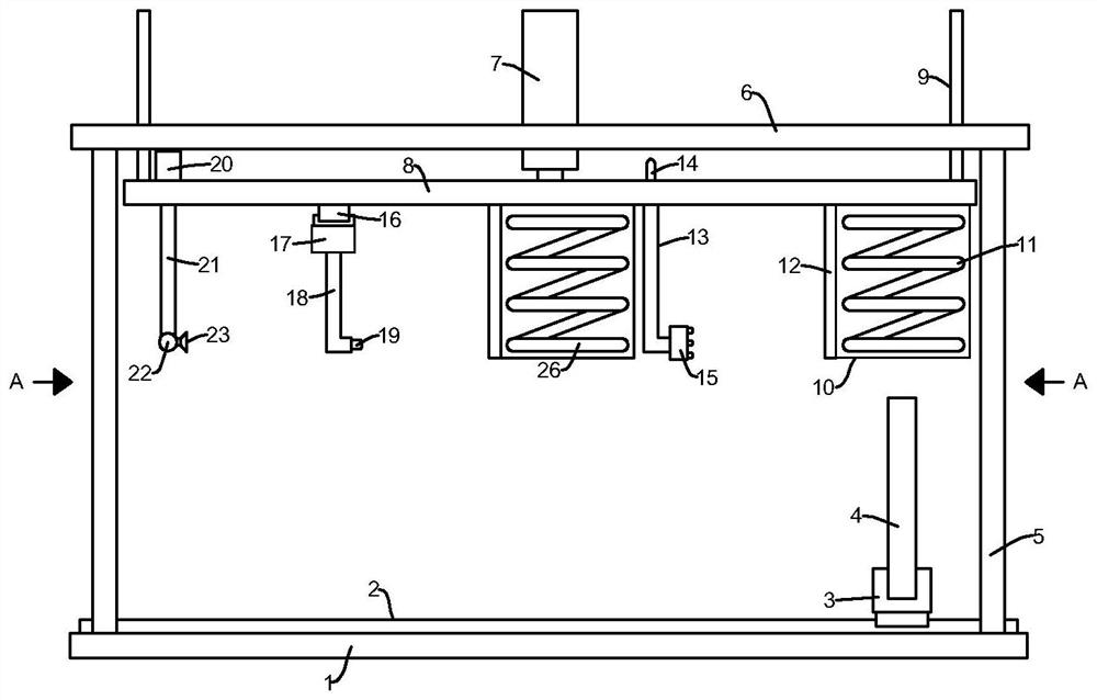
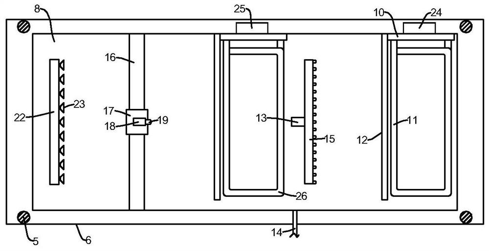
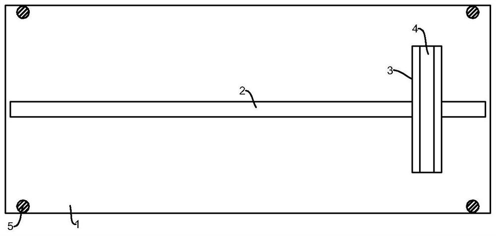
[0018] refer to Figure 1-3 , a continuous heat treatment device for metal layered composite plates, comprising a base plate 1, a first linear motor 2 is fixed on the upper surface of the base plate 1, and an inverted " The clasp plate 3 of the shape of """ is inserted into the clasp plate 3 with a metal layered composite plate 4, and the two ends of the edge of the bottom plate 1 on both sides of the first linear motor 2 are vertically fixed with fixed columns 5, and four A top plate 6 is vertically fixed on one end of the fixed column 5 away from the bottom plate 1, a cylinder 7 is penetrated and fixed at the center of the top plate 6, and a moving plate 8 is vertically fixed on the top of the push rod of the cylinder 7, and the moving plate 8 It is arranged between the bottom plate 1 and the top plate 6, and a high-frequency induction heating mechanism, a surface flame heating mechanism, an electromagnetic induction heating mechanism, a laser heating mechanism and a cooling...

Embodiment 2

[0021] refer to Figure 1-3 , as another preferred embodiment of the present invention, the difference from Embodiment 1 is that both the high-frequency induction heating mechanism and the electromagnetic induction heating mechanism include a fixed plate 10, and the fixed plate 10 is vertically fixed on the opposite side of the moving plate 8 and the bottom plate 1. On the side, one end of the fixing plate 10 is vertically fixed with a shielding plate 12, and the two fixing plates 10 are respectively fixed with an induction coil 11 and an electromagnetic coil 26 corresponding to the metal layered composite plate 4, and the shielding plate 12 can respond to the induction coil. The coil 11 and the electromagnetic coil 26 play a role of shielding, thereby protecting the induction coil 11 and the electromagnetic coil 26. The induction coil 11 and the electromagnetic coil 26 are respectively connected with a first heating power source 24 and a second heating power source through wir...


PUM


Abstract

The invention relates to the technical field of composite board processing, in particular to a continuous heat treatment device for a metal layered composite board. The device comprises a bottom plate, a first linear motor is fixedly arranged on the upper surface of the bottom plate, an inverted [-shaped clamping plate is fixedly arranged on a sliding block of the first linear motor, a metal layered composite board is inserted into the clamping plate, fixing columns are vertically and fixedly arranged at the two ends of the edge of the bottom plate and on the two sides of the first linear motor, a top plate is vertically and fixedly arranged at the ends, away from the bottom plate, of the four fixing columns jointly, an air cylinder is fixedly arranged at the center of the top plate in a penetrating mode, a moving plate is vertically and fixedly arranged at the top end of a push rod of the air cylinder, and the moving plate is arranged between the bottom plate and the top plate. The heating mode is diversified, differential heat treatment can be carried out on metal layered composite boards with different coating metals, and online continuous heat treatment on the metal layered composite boards can be achieved.

Description

technical field [0001] The invention relates to the technical field of composite plate processing, in particular to a continuous heat treatment device for metal layered composite plates. Background technique [0002] Heat treatment is also a key part of the entire metal layered composite sheet production process. After composite, the strength and hardness of the metal layer are increased, and the plasticity is reduced, which is not conducive to subsequent straightening and use requirements. The actual process of heat treatment is to eliminate the internal stress after compounding and improve the plasticity. However, the heat treatment devices currently used for metal layered composite sheets generally only have one heating method, which cannot perform differential heat treatment for different cladding metals, and cannot realize on-line continuous heat treatment of metal composite sheets. SUMMARY OF THE INVENTION [0003] The purpose of the present invention is to solve th...

Claims


Application Information

Patent Timeline
Patent Type & Authority Applications(China)
IPC IPC(8): C21D1/42C21D1/52C21D1/09C21D9/00
CPCC21D1/42C21D1/52C21D1/09C21D9/0081C21D9/0025Y02P10/25
Inventor 安俊博黄伟包仲南徐泷马德高李代明李卫东
Owner OKUMTEC TECH WENZHOU CO LTD
Why Eureka
Try Eureka