Displacement and ventilation type passive house

A replacement ventilation and passive house technology, applied in the field of housing construction, can solve problems such as air turbulence

Pending Publication Date: 2021-05-11
SUZHOU UNIV
View PDF0 Cites 3 Cited by
  • Summary
  • Abstract
  • Description
  • Claims
  • Application Information

AI Technical Summary

Problems solved by technology

[0004] Ventilation methods such as upward ventilation and upward ventilation will cause air turbulence, which can only dilute the indoor stale air, and cannot prevent the stale air and fresh air from staying indoors after mixing.

Method used


Image

  • Displacement and ventilation type passive house
  • Displacement and ventilation type passive house
  • Displacement and ventilation type passive house

Examples


Embodiment 1

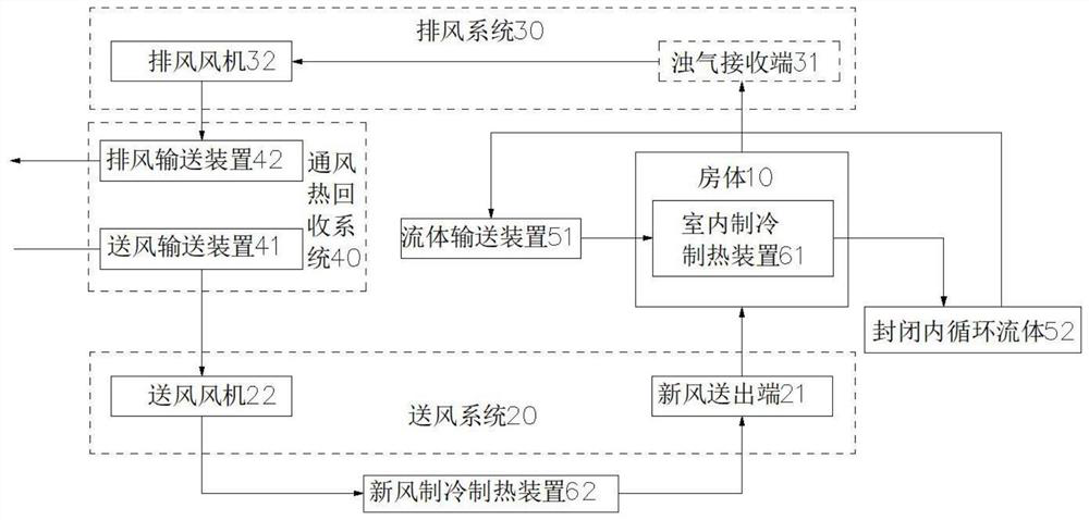
[0032] see Figure 3 to Figure 4 , as shown in the legend therein, a passive house with displacement ventilation, comprising:

[0033] A sealed heat preservation room body 10, one or more personnel gathering belts are arranged in the sealed heat preservation room body 10;

[0034] The air supply system 20, the air supply system 20 inputs fresh air to the inside of the sealed and heat-insulated room body 10, and the air-supplied system 20 includes a fresh air delivery end 21 communicated with the inside of the sealed and insulated room body 10;

[0035] Exhaust system 30, the exhaust system 30 discharges the air containing dirty air inside the sealed and heat-insulating room body 10, and the exhaust system 30 includes a dirty air receiving end 31 communicating with the inside of the sealed and heat-insulated room body 10;

[0036] The ventilation heat recovery system 40, the ventilation heat recovery system 40 includes the air supply conveying device 41 communicated with the i...

Embodiment 2

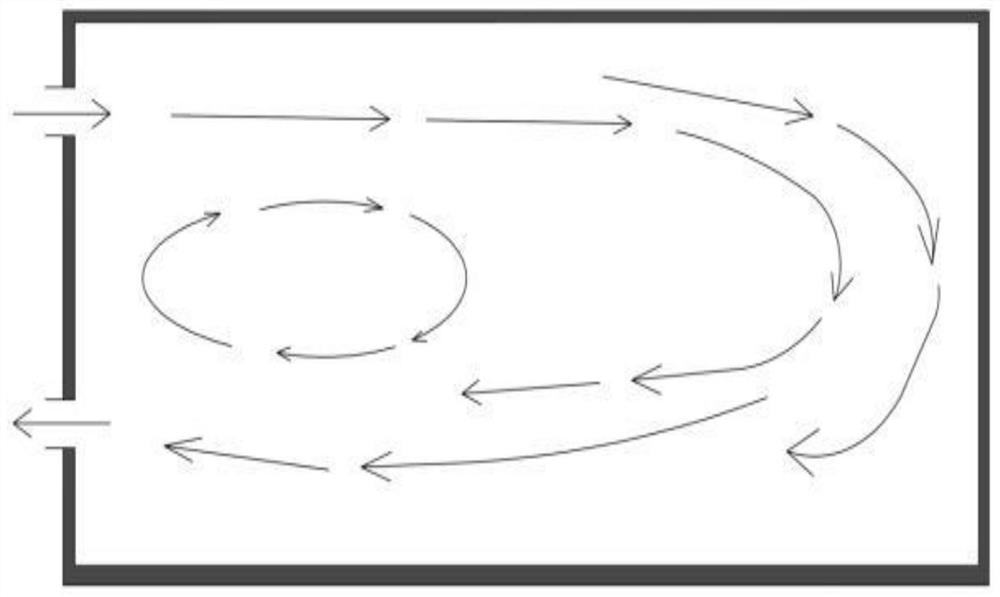
[0056] see Figure 5 , as shown in the legend, the rest is the same as the first embodiment, the difference is that there is a band-shaped accumulation area of ​​heat source distributed in the sealed and heat-insulated room, and the fresh air delivery end is set on the ground or corner of the sealed and heat-insulated room or the lower end of the wall. The receiving end of the turbid air is arranged on the top wall or the upper end of the wall of the sealed and insulated room.

[0057] In this embodiment, in a small office / room, cool air with a speed of less than 0.2m / s is sent from the bottom of one side of the room, through the heat radiation at the bottom, and the heat provided by the heat source of the human body in the room. The hot and dirty air together reaches the top area of ​​the ceiling and then exits the room over the other side. There is almost no polluting gas in the work area, avoiding indoor cross-infection and improving the health of the indoor environment, w...


PUM


Abstract

The invention discloses a displacement and ventilation type passive house, which comprises a sealed heat insulating house body, an air supply system, an exhaust system, a ventilation heat recycling system, an environment source heat exchange system and a heating and refrigerating system, wherein the air supply system comprises a fresh air discharging end communicating with the interior of the sealed heat insulating house body; the fresh air discharging end is lower than the mouth and noise of a human body in a personnel gathering area; the air exhaust system comprises a foul air receiving end communicating with the interior of the sealed heat insulating house body; the foul air receiving end is higher than the mouse and noise of a human body in a personnel gathering area; the refrigerating and heating system comprises an indoor refrigerating and heating device and a fresh air refrigerating and heating device, wherein the indoor refrigerating and heating device is used for refrigerating or heating air in the sealed heat insulating house body to a set temperature; and the fresh air refrigerating and heating device is used for refrigerating and heating fresh air supplied by the air supply system to a temperature lower than the set temperature. The displacement and ventilation type passive house disclosed by the invention adopts a way that air is supplied from the lower portion and exhausted from the upper portion and implements low-speed air supply, thus indoor air quality replacement is facilitated.

Description

technical field [0001] The invention belongs to the technical field of building construction, and in particular relates to a replacement ventilation passive house. Background technique [0002] Professor Adamson of DeLong University in Sweden and Dr. Fest of Germany first proposed the concept of passive house in 1988. properties to maintain a comfortable interior thermal environment for the building. In 1991, the first "passive house" was built in Darmstadt, Germany. Then Dr. Fest established the "Passive House" Institute (PHI) in Darmstadt, Germany in 1996. In 2015, the German Passive Research Center further improved the certification standards for passive houses, which are divided into three levels: "Classic", "Plus" and "Premium". The latest 2020 version of Germany's "Building Energy Law" stipulates that there are three requirements for near-zero energy buildings: 1) The energy consumption of heating, cooling, ventilation, hot water lighting, etc. of the building must ...

Claims


Application Information

Patent Timeline
Patent Type & Authority Applications(China)
IPC IPC(8): F24F7/003F24F7/007F24F8/108F24F11/64F24F11/72F24F11/83F24F12/00F24D13/00F25B23/00F24F110/10
CPCF24F7/007F24F11/64F24F11/72F24F11/83F24F12/006F24D13/00F25B23/00F24F2110/10Y02B30/56Y02B30/70
Inventor 吴捷沈景华陈守恭彭旭辉田雨李东会田真韩冬辰薛朝阳李晓晗张洁徐樑
Owner SUZHOU UNIV
Why Eureka
Try Eureka