Supercharge Your Innovation With Domain-Expert AI Agents!

Arrangement in a subscriber line interface circuit

A line voltage, telephone line technology, applied in the direction of measuring devices, line transmission parts, electric pulse generator circuits, etc., can solve problems such as difficulty in resolution

Inactive Publication Date: 2003-11-12
INFINEON TECH AG
View PDF0 Cites 0 Cited by
  • Summary
  • Abstract
  • Description
  • Claims
  • Application Information

AI Technical Summary

Problems solved by technology

[0005] When the length of the pulse is to be measured, it is difficult to achieve a good resolution because the pulse length determines the measurement time period

Method used


Image

  • Arrangement in a subscriber line interface circuit
  • Arrangement in a subscriber line interface circuit
  • Arrangement in a subscriber line interface circuit

Examples


Embodiment approach

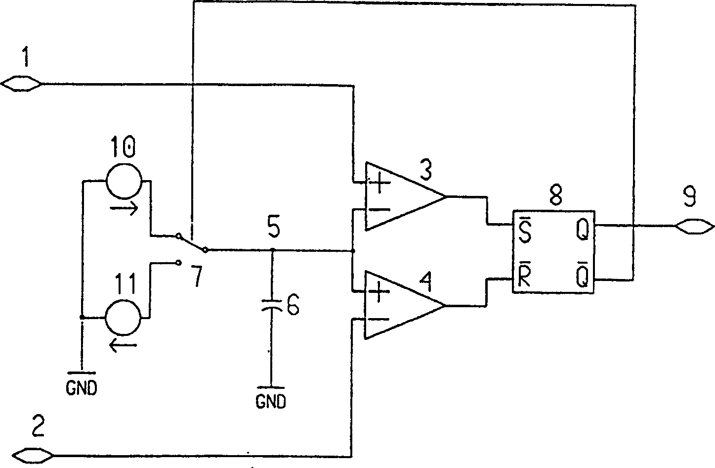
[0021] figure 1 A first embodiment of the device according to the invention is described, which generates a signal for determining the line voltage in a subscriber line interface connected to a telephone line having a high-voltage line and a low-voltage line.

[0022] exist figure 1 Inside the device, the high-voltage line or A line is connected to terminal 1, and the low-voltage line or B line is connected to terminal 2.

[0023] Terminal 1 is connected to the (+)-input terminal of comparator 3 and terminal 2 is connected to the (-)-input terminal of comparator 4 . The (-)-input terminal of comparator 3 and the (+)-input terminal of comparator 4 are connected to each other and the interconnection point is connected to node 5 . The capacitor 6 is connected to each other between the node and the ground GND.

[0024] The switching unit of the voltage-controlled switch 7 is connected to the node 5 and is switched between its upper and lower positions by means of a signal contr...


PUM


Abstract

In a subscriber line interface circuit connected to a telephone line having a high potential wire and a low potential wire, an arrangement for generating a signal for determining the line voltage comprises means (7, 10, 11) for alternately charging a capacitor (6), by means of a first DC current, to a first voltage, and discharging the capacitor (6), by means of a second DC current, to a second voltage. Hereby, a sawtooth wave having an amplitude corresponding to the difference between the first and second voltages is produced. This sawtooth wave is converted to a pulse train related to the line voltage, from which the line voltage can be determined.

Description

technical field [0001] The present invention relates generally to subscriber line interface circuits, and more particularly to means for determining line voltage within a subscriber line interface circuit. Background technique [0002] In order to be able to adjust the hybrid interface parameters and gains within the telephone circuit by means of the microprocessor on the line interface board to obtain good echo cancellation for different lengths of telephone lines and also for some testing purposes, knowing the length of each telephone line is necessary. [0003] One method of estimating the length of the line is to measure the line voltage, ie the voltage present between the line and the telephone when the connection is established. [0004] It is known to generate pulses with a length corresponding to the line voltage. The length of this pulse is then measured by a microprocessor on the line interface board in order to obtain information about the ...

Claims


Application Information

Patent Timeline
Patent Type & Authority Patents(China)
IPC IPC(8): G01R15/14G01R19/252H03K3/0231H04B3/46H04B3/48
CPCH04B3/48G01R19/252H04B3/46H03K3/021G01R15/14H04M1/24
Inventor A·埃梅里克斯H·赫尔贝里M·伊斯雷尔森C·-H·马尔姆格伦
Owner INFINEON TECH AG
Features
  • R&D
  • Intellectual Property
  • Life Sciences
  • Materials
  • Tech Scout
  • Unparalleled Data Quality
  • Higher Quality Content
  • 60% Fewer Hallucinations
Learn More