Unmanned aerial vehicle for photovoltaic power generation inspection

A photovoltaic power generation and unmanned aerial vehicle technology, applied in the field of unmanned aerial vehicles, can solve the problems of low efficiency of photovoltaic panel inspection, complex installation environment of high-voltage power grid, and high cost of manual inspection

Pending Publication Date: 2021-05-11
拓航科技有限公司
View PDF4 Cites 1 Cited by
  • Summary
  • Abstract
  • Description
  • Claims
  • Application Information

AI Technical Summary

Problems solved by technology

After electricity is generated, it needs to be transmitted through the high-voltage power grid. For safety, the high-voltage power grid is mostly installed in the sky, and for valleys, hills and other areas, the installation environment of the high-voltage power grid is more complicated, which makes it very inconvenient to detect the power grid, resulting in If the problems on the power grid cannot be found in time, it is easy to cause larger problems and cause the power grid to be interrupted, resulting in greater economic losses
[0004] Photovoltaic power stations have the characteristics of large area, large number of photovoltaic panels, and dense distribution of photovoltaic panels, which actually leads to low efficiency and high cost of photovoltaic panel inspection
Among them, manual inspection is extremely dependent on manpower, and the photovoltaic power station has a huge area, the cost of manual inspection is high, the work efficiency is low, the safety factor is low, and it is not convenient for people to use
For related technical problems, no effective solutions have been proposed

Method used


Image

  • Unmanned aerial vehicle for photovoltaic power generation inspection
  • Unmanned aerial vehicle for photovoltaic power generation inspection
  • Unmanned aerial vehicle for photovoltaic power generation inspection

Examples


Embodiment Construction

[0026] Embodiments of the present invention are described below through specific examples, and those skilled in the art can easily understand other advantages and effects of the present invention from the content disclosed in this specification. The present invention can also be implemented or applied through other different specific implementation modes, and various modifications or changes can be made to the details in this specification based on different viewpoints and applications without departing from the spirit of the present invention. It should be noted that, in the case of no conflict, the following embodiments and features in the embodiments can be combined with each other.

[0027] It should be noted that the diagrams provided in the following embodiments are only schematically illustrating the basic ideas of the present invention, and only the components related to the present invention are shown in the diagrams rather than the number, shape and number of componen...


PUM


Abstract

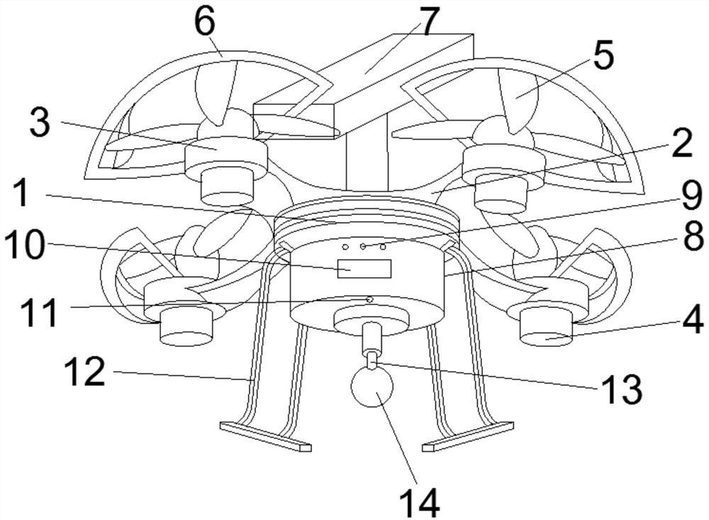
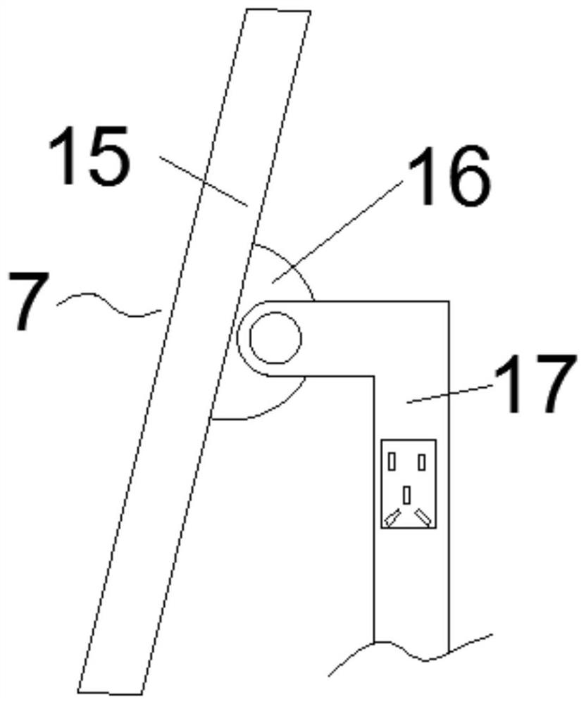
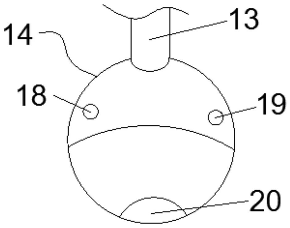
The invention discloses an unmanned aerial vehicle for photovoltaic power generation inspection. The unmanned aerial vehicle comprises an unmanned aerial vehicle body, wherein motor fixing bases are fixedly installed on the periphery of the unmanned aerial vehicle body through supporting frames, driving motors are fixedly installed on the motor fixing bases, rotor wings are fixedly installed on power output shafts of the driving motors, the top part of the unmanned aerial vehicle body is provided with a power supply device, the power supply device comprises a photovoltaic panel, an adjusting part and a supporting rod, the bottom part of the unmanned aerial vehicle body is provided with a control device, the outer surface of the control device is provided with a wireless signal transceiver, the bottom part of the control device is provided with an information acquisition device through a rotating part, the information acquisition device comprises an infrared distance measurement detection probe, a sound wave detection probe and a camera, a heat dissipation device is arranged on one side of the unmanned aerial vehicle body, and a control chip is arranged in the control device. According to the unmanned aerial vehicle, remote wireless detection is realized, the operation is convenient, the working efficiency of photovoltaic power generation inspection is improved, and the labor intensity is reduced.

Description

technical field [0001] The invention relates to the technical field of unmanned aerial vehicles, in particular to an unmanned aerial vehicle for inspection of photovoltaic power generation. Background technique [0002] With the rapid development of the domestic solar photovoltaic power generation industry, the production capacity of photovoltaic power generation panels and related components has increased rapidly. Among them, the hot spot phenomenon is a common problem of photovoltaic panels and components, and the formation of hot spots is mainly caused by two factors: the internal resistance and the undercurrent of the battery itself, which manifests as local high temperature of the photovoltaic panel, which will affect Photovoltaic panel power generation efficiency. [0003] With the development of society, electricity has gradually become the main energy source for people's lives. Wind power, thermal power, geothermal power, nuclear power, etc. are continuously providi...

Claims


Application Information

Patent Timeline
Patent Type & Authority Applications(China)
IPC IPC(8): G05D1/10
CPCG05D1/101
Inventor 方磊华亿明倪娜娜杨杰
Owner 拓航科技有限公司
Why Eureka
Try Eureka