Quantitative cutting machine for rough blank in model clay production
A quantitative segmentation and clay technology, which is applied to ceramic molding machines, ceramic material production, manufacturing tools, etc., can solve problems such as inaccuracy and troublesome operation
- Summary
- Abstract
- Description
- Claims
- Application Information
AI Technical Summary
Problems solved by technology
Method used
Image

Examples
Embodiment 1
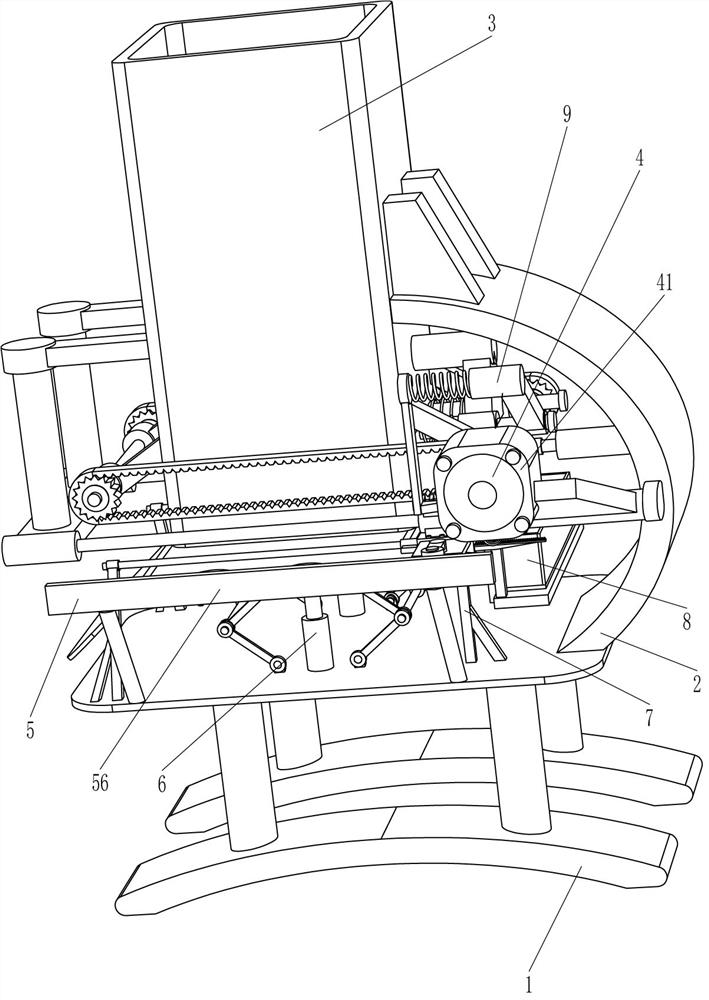
[0079] A kind of quantitative splitting machine for rough embryo blocks for model clay production, such as figure 1 As shown, it includes a base 1, a mounting frame 2, a feeding pipe 3, a driving mechanism 4, a cutting mechanism 5, a thickness adjustment mechanism 6 and a discharge mechanism 7. The right side of the top of the base 1 is connected to the mounting frame 2, and the upper part of the mounting frame 2 The left side is connected with the feeding pipe 3, the driving mechanism 4 is connected to the feeding pipe 3, the cutting mechanism 5 is connected between the base 1 and the feeding pipe 3, the cutting mechanism 5 is connected with the driving mechanism 4, and the top of the mounting frame 2 is connected in the middle There is a thickness adjustment mechanism 6, and a discharge mechanism 7 is connected between the cutting mechanism 5 and the installation frame 2.
[0080] When people need to quantitatively divide the clay, first adjust the thickness of the clay cutt...
Embodiment 2
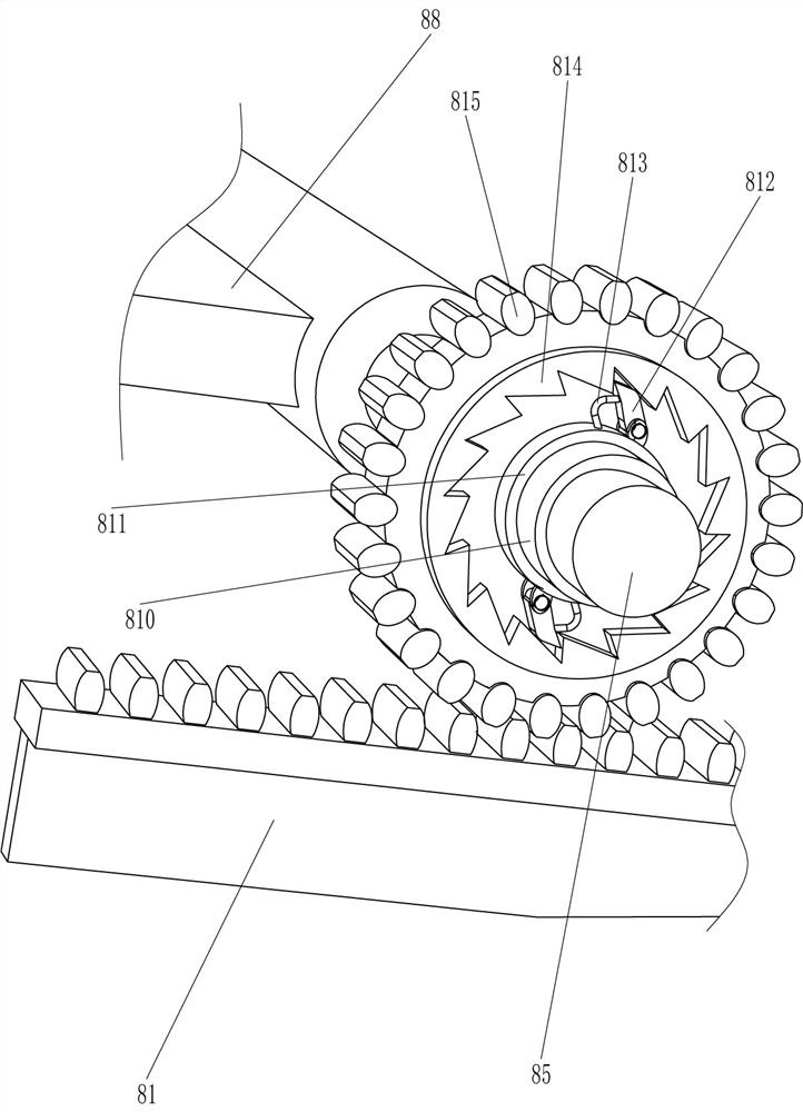
[0082] On the basis of Example 1, such as Figure 1-4 As shown, the driving mechanism 4 includes a reduction motor 41, a fixed rod 42, a rotating shaft 43, a synchronous wheel 44 and a synchronous belt 45, and two fixed rods 42 are connected to the left and right sides of the lower part of the feeding pipe 3, and the fixed rod 42 on the same side All rotation type is connected with rotating shaft 43 between, rotating shaft 43 front and rear sides all are connected with synchronous wheel 44, are all connected with synchronous belt 45 between horizontal synchronous wheel 44, and the parts right front side of cutting mechanism 5 is connected with decelerating motor 41, decelerating motor 41 output shafts are connected with the rotating shaft 43 front side on the right side.
[0083] After adjusting the thickness of the clay cutting, control the geared motor 41 to rotate forward, drive the rotating shaft 43, the synchronous wheel 44 and the synchronous belt 45 to rotate forward, a...
Embodiment 3
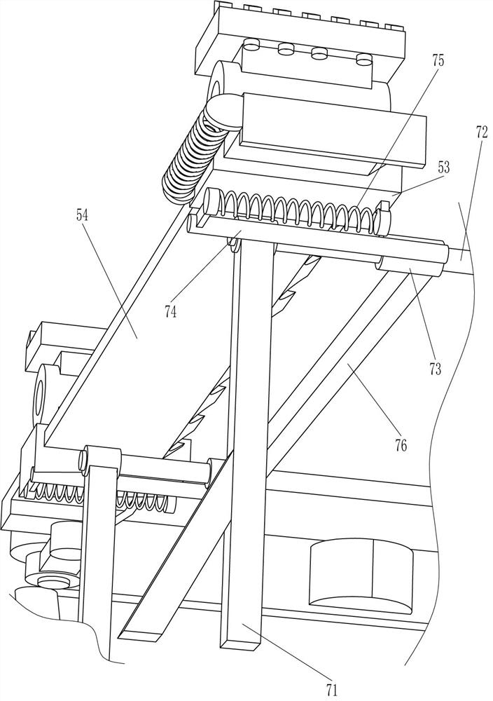
[0089] On the basis of Example 2, such as Figure 4-8 As shown, the discharge mechanism 7 includes a fixed frame 71, a slide bar 72, a sliding sleeve 73, an extension rod 74, a first spring 75 and a push plate 76, and the top, left, and right sides of the base 1 are connected with a fixed frame 71. The horizontal fixed frame 71 is connected with a slide bar 72, and the slide bar 72 is slidably connected with a sliding sleeve 73, and the outer side of the sliding sleeve 73 is connected with an extension rod 74, and the right side of the extension rod 74 and the flat hole sleeve on the same side A first spring 75 is connected between the 53, and a push plate 76 is connected between the sliding sleeves 73.
[0090] When the flat hole sleeve 53 moves to the left to drive the cutter 54 to move to the left, because the clay is not cut off, the push plate 76 is blocked, and now the first spring 75 is stretched, and when the cutter 54 moves to the left After cutting the clay, under t...
PUM
 Abstract
Description
Claims
Application Information
 - R&D
- Intellectual Property
- Life Sciences
- Materials
- Tech Scout
- Unparalleled Data Quality
- Higher Quality Content
- 60% Fewer Hallucinations
Browse by: Latest US Patents, China's latest patents, Technical Efficacy Thesaurus, Application Domain, Technology Topic, Popular Technical Reports.
© 2025 PatSnap. All rights reserved.Legal|Privacy policy|Modern Slavery Act Transparency Statement|Sitemap|About US| Contact US: help@patsnap.com