Supercharge Your Innovation With Domain-Expert AI Agents!

Adjustable grating and lift pump well structure

An adjustable, lifting pump technology, applied in water/sewage treatment, water/sludge/sewage treatment, chemical instruments and methods, etc., can solve the problem of increasing labor intensity, cleaning frequency and cost of workers, terminal pipe network and Improve the problems of water pump blockage, water inlet pipe network and water pump blockage, etc., to achieve the effect of simplifying daily cleaning work, solving the problem of reducing pipe network and water pump blockage, and reducing processing load

Pending Publication Date: 2021-05-14
广东省广业环保服务有限公司
View PDF0 Cites 0 Cited by
  • Summary
  • Abstract
  • Description
  • Claims
  • Application Information

AI Technical Summary

Problems solved by technology

The waste water flows directly into the lift pump well, and the interception effect of the grid of the pump well is limited, which often causes blockage of the water inlet pipe network and the water pump, making cleaning very difficult, increasing the labor intensity, cleaning frequency and cost of workers cleaning
At present, the inlet of the lift pump well at the front end of most treatment facilities is directly connected to the terminal of the wastewater pipe network. The grid installed on the lift pump well cannot fully meet the interception of floating objects in the waste water pipe network because of the large grid gap and the horizontal distribution of long holes. , leading to blockage of terminal pipe network and lift pump

Method used


Image

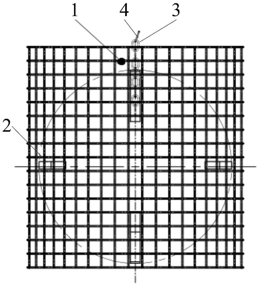
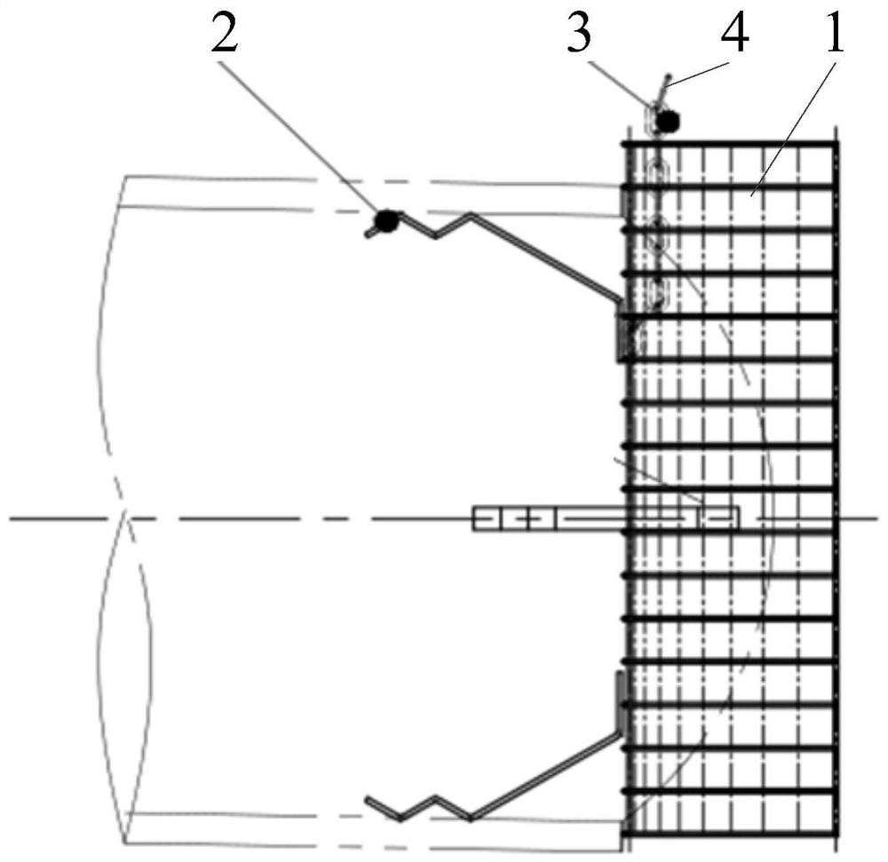
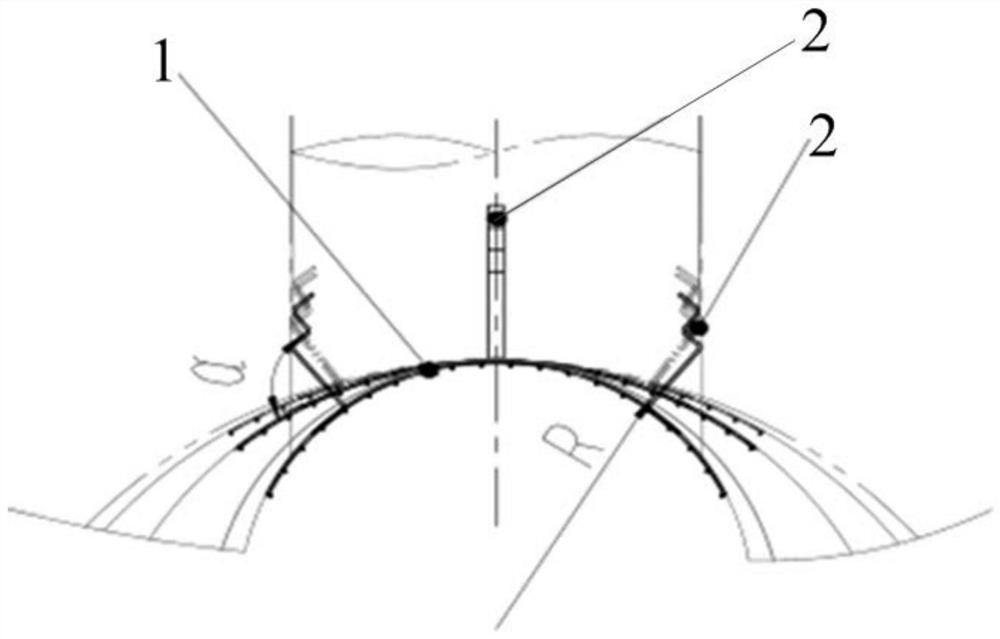
  • Adjustable grating and lift pump well structure
  • Adjustable grating and lift pump well structure
  • Adjustable grating and lift pump well structure

Examples


Embodiment Construction

[0022] The following will clearly and completely describe the technical solutions in the embodiments of the present invention with reference to the accompanying drawings in the embodiments of the present invention. Obviously, the described embodiments are only part of the embodiments of the present invention, not all of them. Based on the embodiments of the present invention, all other embodiments obtained by persons of ordinary skill in the art without creative efforts fall within the protection scope of the present invention.

[0023] It should be noted that all directional indications (such as up, down, left, right, front, back...) in the embodiments of the present invention are only used to explain the relationship between the components in a certain posture (as shown in the accompanying drawings). Relative positional relationship, movement conditions, etc., if the specific posture changes, the directional indication will also change accordingly.

[0024] In addition, the ...


PUM


Abstract

The utility model relates to an adjustable grating and lift pump well structure, the adjustable grating comprises a grid mesh, the grid mesh is provided with a tensioning support leg, the tensioning support leg abuts against the well wall of an inspection well, the radian of the grid mesh is adjusted to make the grid mesh consistent with the well body of the inspection well, the angle of the tensioning support leg abutting against the well wall is adjusted, and the tensioning support leg can be adjusted to be consistent with the well wall of the inspection well. The grid mesh is tightly attached to the well wall, so that the problems of form and position deviation, deformation and irregularity of construction and manufacturing of different inspection wells with the same flow outlet are solved, floating objects in waste water are effectively intercepted, the tensioning supporting feet elastically abut against the well wall, the field adjustability is high, disassembly and assembly are convenient, multi-stage interception is implemented by using the adjustable grids with different drift diameters, solid floating objects in waste water can be effectively intercepted, the solid floating objects are intercepted in the inspection well, daily operation and maintenance can be completed only by regularly cleaning the inspection well and the adjustable grating, the workload of operation and maintenance is greatly reduced, the treatment load of subsequent facilities is reduced, and the treatment efficiency of the facilities is improved.

Description

technical field [0001] The invention relates to the technical field of sewage treatment, in particular to an adjustable grid and lift pump well structure. Background technique [0002] In the design of existing sewage treatment equipment and facilities, because the installation space of the inspection well is limited, the pipe network does not design a slag blocking device, but the actual wastewater contains a large amount of floating and suspended matter (such as fibers, hair, fruit peels, plastic products, etc.) Wait). The waste water flows directly into the lift pump well, and the interception effect of the grid of the pump well is limited, which often causes blockage of the water inlet pipe network and the water pump, making cleaning very difficult, increasing the labor intensity, cleaning frequency and cost of workers cleaning. At present, the inlet of the lift pump well at the front end of most treatment facilities is directly connected to the terminal of the wastewat...

Claims


Application Information

Patent Timeline
IPC IPC(8): C02F1/00
CPCC02F1/00
Inventor 周华王银生曾祥波陈旭怀廖侃许多芬苏志勇詹成钟泽桦黄书豪
Owner 广东省广业环保服务有限公司
Features
  • R&D
  • Intellectual Property
  • Life Sciences
  • Materials
  • Tech Scout
  • Unparalleled Data Quality
  • Higher Quality Content
  • 60% Fewer Hallucinations
Learn More